2-49
87519804 NA
Issued 11-06
Bur
CHAPTER 2 - 667TA ENGINE OVERHAUL
ENGINE REPAIR MANUAL
BS06K064
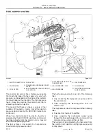
Figure 2-63
The figure above shows the low pressure fuel
passages inside the pump. The figure shows the
main plungers supply passage (4), the individual
plunger supply passages (1, 3, 6), the passages
utilized for lubrication of the pump (2), the high
pressure regulator (5), the 5 bar (72 psi) pressure
regulator valve (8) and the fuel discharge passage
(7).
The high pressure regulator (5) determines the
quantity of fuel which the high pressure plungers
deliver to the common rail. Excess fuel flows out
through passage (9).
The regulator valve (8), is designed to maintain a
constant pressure of 5 bar (72 psi.) at the high
pressure regulator inlet.
BS06K065
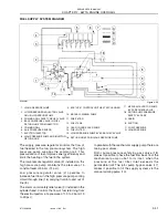
Figure 2-64
The figure above shows the fuel flow under high
pressure running through the exhaust galleries of the
pumping elements.
THEORY OF OPERATION
The cylinder is filled through the cap intake valve
only if the supply pressure is suitable to open the
delivery valves set on the pumping elements about
2 bars (29 psi.).
The amount of fuel supplying the high pressure pump
is metered by the high pressure regulator. The high
pressure regulator is controlled by the EDC7UC31
control unit through a PWM (pulse width modulated)
signal.
When fuel is se nt to a pump ing elem ent, th e
corresponding piston is moving downwards (suction
stroke). When the piston stroke is reversed, the
intake valve closes and the fuel in the pumping
element chamber, is compressed into the rail.
The generated pressure makes the exhaust valve
open and the compressed fuel reaches the high
pressure circuit.
The pumping element compresses the fuel till the top
dead center (delivery stroke) is reached. Afterwards,
the pressure decreases till the exhaust valve is
closed.
The pumping element piston goes back towards the
bottom dead center and the remaining fuel is
decompressed.
1. INLET TO HIGH PRESSURE PLUNGERS
2. PUMP LUBRICATION PASSAGES
3. INLET TO HIGH PRESSURE PLUNGERS
4. MAIN PLUNGERS SUPPLY PASSAGE
5. HIGH PRESSURE REGULATOR VALVE
6. INLET TO HIGH PRESSURE PLUNGERS
7. CHARGE PRESSURE REGULATOR DRAIN PASSAGE
8. CHARGE PRESSURE 5 BAR (72 PSI) REGULATOR VALVE
9. FUEL DISCHARGE FROM HIGH PRESSURE REGULATOR
VALVE INLET
1
9
3
4
7
6
2
5
8
1. FUEL EXHAUST FLUE
2. FUEL EXHAUST FLOWING FROM PUMP WITH
CONNECTOR TO HIGH PRESSURE LINE FOR
COMMON RAIL
3. FUEL EXHAUST GALLERY
3
2
1
Summary of Contents for 667TA/EBF
Page 4: ...SECTION 1 ENGINE REPAIR MANUAL II Issued 11 06 Bur 87519804 NA NOTES ...
Page 8: ...1 2 Issued 11 06 Bur 87519804 NA CHAPTER 1 DIAGNOSTICS ENGINE REPAIR MANUAL NOTES ...
Page 16: ...1 10 Issued 11 06 Bur 87519804 NA CHAPTER 1 DIAGNOSTICS ENGINE REPAIR MANUAL NOTES ...
Page 22: ...2 4 Issued 11 06 Bur 87519804 NA CHAPTER 2 667TA ENGINE OVERHAUL ENGINE REPAIR MANUAL NOTES ...
Page 144: ...3 2 Issued 11 06 Bur 87519804 NA CHAPTER 3 CHARGING AND START UP ENGINE REPAIR MANUAL NOTES ...
Page 150: ...3 8 Issued 11 06 Bur 87519804 NA CHAPTER 3 CHARGING AND START UP ENGINE REPAIR MANUAL NOTES ...


