2-100
Issued 11-06
Bur
87519804 NA
CHAPTER 2 - 667TA ENGINE OVERHAUL
ENGINE REPAIR MANUAL
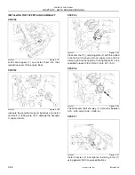
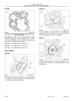
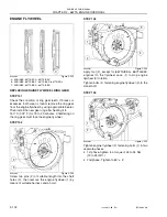
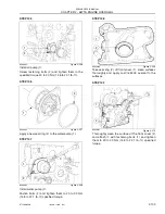
STEP 94
BS06K322
Figure 2-195
DIAGRAM FOR TIGHTENING THE REAR TIMING GEAR CASE
FASTENING BOLTS
Reconnect the case (1) to the engine block. Screw
the fastening bolts in the same position found at
removal and tighten them to the following torque
values in the sequence shown below.
Bolts M12
65 to 89 Nm (48 to 66 lbf. -ft.)
Bolts M8
20 to 28 Nm (15 to 21 lbf.- ft.)
Bolts M10
42 to 52 Nm (31 to 38 lbf.- ft.)
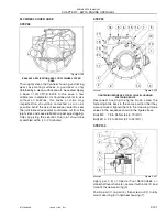
VALVE TIMING
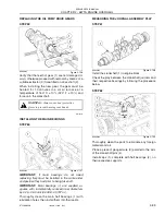
STEP 95
BS06K323
Figure 2-196
Mark with a felt tip pen the tooth (3) of the drive gear
(1) installed on the crankshaft (2), having the mark
(
→)
for timing on the side surface.
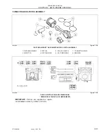
STEP 96
BS06K324
Figure 2-197
Turn crankshaft (4) and camshaft (1) so that when
installing the driven gear (2) on the camshaft the
marks on the gears (2 and 3) are aligned.
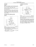
STEP 97
BS06K325
Figure 2-198
Install fastening bolts (1) fastening gear (2) to
camshaft (3) and tighten using general bolt torque
specifications.
1
2
1
3
1
4
3
2
1
2
3
Summary of Contents for 667TA/EBF
Page 4: ...SECTION 1 ENGINE REPAIR MANUAL II Issued 11 06 Bur 87519804 NA NOTES ...
Page 8: ...1 2 Issued 11 06 Bur 87519804 NA CHAPTER 1 DIAGNOSTICS ENGINE REPAIR MANUAL NOTES ...
Page 16: ...1 10 Issued 11 06 Bur 87519804 NA CHAPTER 1 DIAGNOSTICS ENGINE REPAIR MANUAL NOTES ...
Page 22: ...2 4 Issued 11 06 Bur 87519804 NA CHAPTER 2 667TA ENGINE OVERHAUL ENGINE REPAIR MANUAL NOTES ...
Page 144: ...3 2 Issued 11 06 Bur 87519804 NA CHAPTER 3 CHARGING AND START UP ENGINE REPAIR MANUAL NOTES ...
Page 150: ...3 8 Issued 11 06 Bur 87519804 NA CHAPTER 3 CHARGING AND START UP ENGINE REPAIR MANUAL NOTES ...

