13
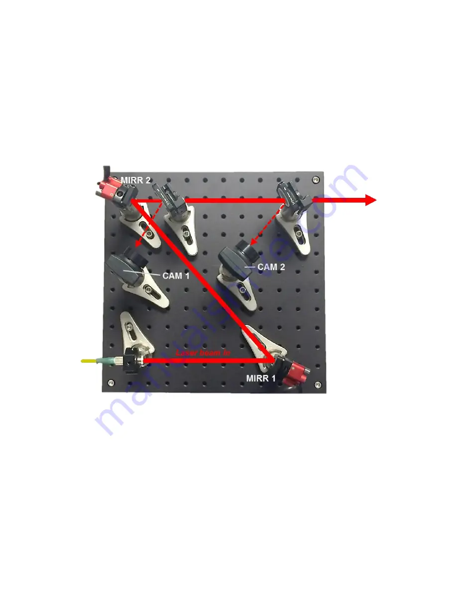
Typical values might be 50 cm between mirrors, 50 cm between cameras, and 10
cm between Mirror 2 and Camera 1.
Note that the system can tolerate a wide range of deviation from these guidelines.
In general, however, a larger spacing between cameras will allow for tighter
pointing control, since the maximum pointing drift under closed-loop operation
will be determined by the ratio of the Target size to the separation between the
cameras. For example, for a 30-μm Target, pointing drift will be limited to 60
μrad for a 0.5-m separation and 30 μrad for a 1-m separation.
Figure 10. Example physical layout of mirrors and cameras for GuideStar II
system.
To optimize performance, Camera 2 can be positioned so as to image a plane
equivalent to the users working plane. This can be accomplished by setting the
distance between the second pickoff and the working plane comparable to the
distance between the second pickoff and Camera 2’s object plane, which is about
4 cm in front of the lens. By doing this the beam position data and image shown
by the GuideStar II software are essentially those of the working plane.


