


User’s Manual
Wireless Serial Server GW5120
Copyright © 2009 Neteon Technologies, Inc.
All rights reserved.
70
9
RI
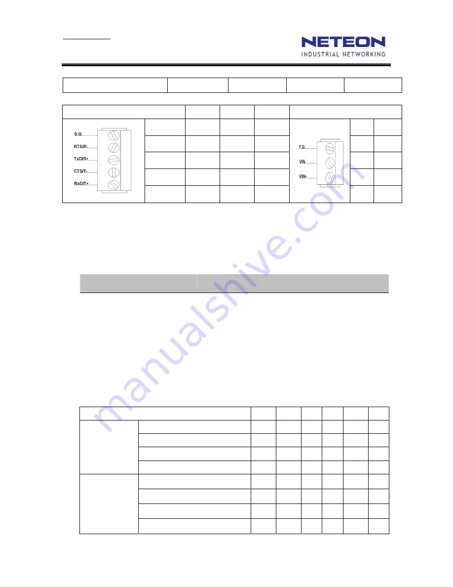
Terminal block pin assignments for Serial and Power
5-pin for serial connections
RS-232
RS-485
RS-422
3-pin for Power input
SG
GND GND GND
FG
FG
RTS/R-
RTS Data- R-
Vin-
GND
TxD/R+
TxD Data+ R+
Vin+
9~48V
CTS/T-
CTS T-
RxD/T+
RxD T+
Note: RS-485 2 or 4 pins assignments of DB9 connector are different from those of
Mini DIN connector.
D.4 Beep & LED Status
Startup status
Message
Description
^==^========^^^
(5sec)
Startup OK and AP firmware is enabled
Buzzer indication: “ ^ “ : Beep twice “ = “ : Beep off
Wireless Signal Strength status
The BSS quality can be detected by LED indicator on GW5120. On running time, pressed default
key and then released, one of the specified actions below shall be done that depend on the released
time after you heard how many beeps. BSS quality is indicated by count of LEDs as shown below.
RSSI LEDs Message:
○
Off
●
On
☼
blinking
Operations
Status* LED1 LED2
LED3 LED4 LED5
Connecting
Search AP
(sequentially blinking)
☼
☼
☼
☼
☼
☼
Connected AP/ Get assigned IP
☼
☼
☼
☼
☼
☼
Not matched SSID
☼
Not available IP
☼
☼
Connected
Signal Strength is less 20%
●
Bad Signal Strength (20%)
●
●
Poor Signal Strength (40%)
●
●
●
Fair Signal Strength (60%)
●
●
●
●