9
SafeGuard Controller User Manual
MAN-0115 Rev 0
causing an
acknowledged
steady on condition. Operators should recognize
new
alarms
by a flashing LED.
Alarm Reset
also
acknowledges
, or deactivates, the horn relay until
another new alarm occurs.
All relays are rated at 5 Amp for 28 VDC and 250 ~VAC
RESISTIVE
loads.
IMPORTANT: Appropriate diode (DC loads) or MOV (AC loads) snubber
devices must be installed with inductive loads to prevent RFI noise spikes. Relay
wiring should be kept separate from low level signal wiring.
2.2.3
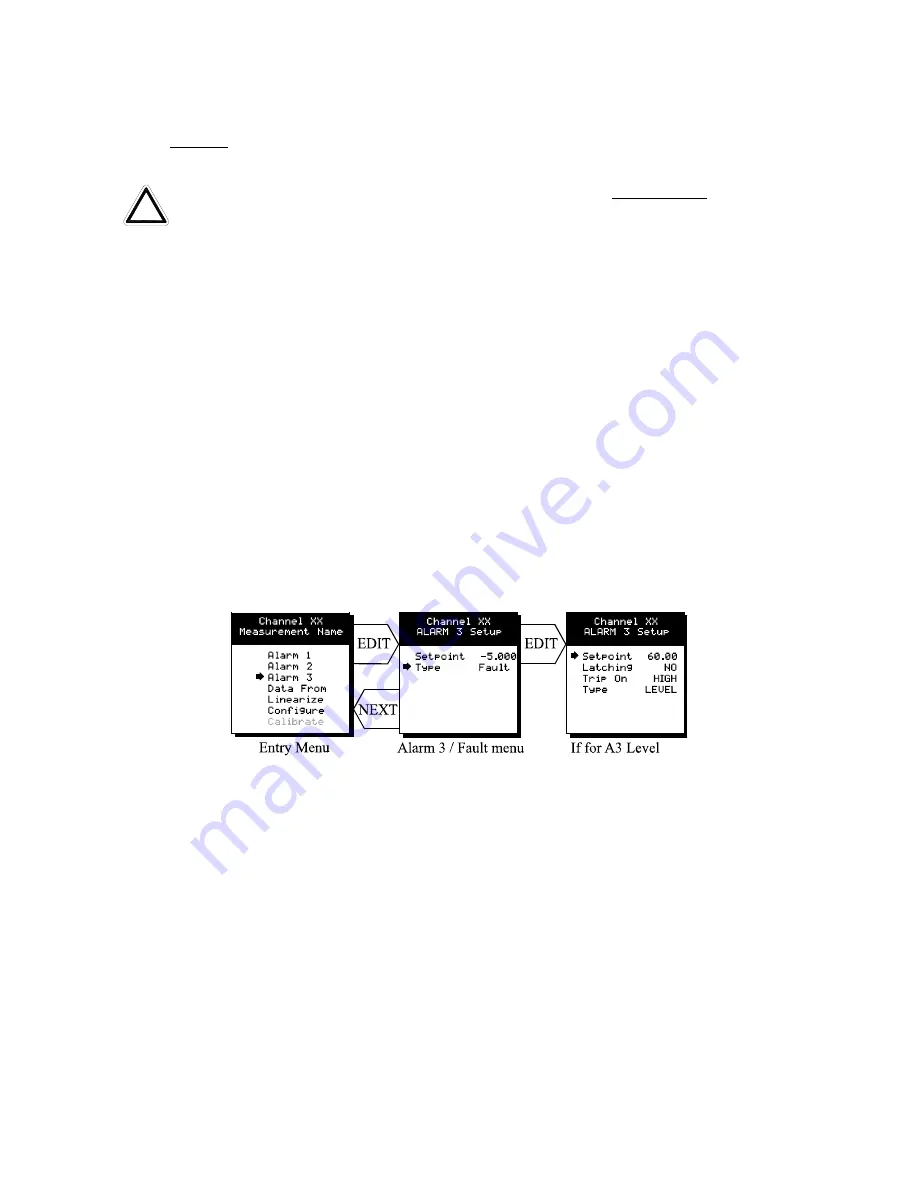
ALARM 3 / FAULT ALARM MENU
The discrete channel alarms identified as Alarm 3/Fault may be configured either as a 3
rd
level alarm, or, as a Fault alarm indicating the input is out of range in the negative
direction. When used as a level alarm, features such as on / off delays, latching, and trip
direction are also available. It is important to understand that though discrete channel
alarms (LED’s & optional discrete relays) may be set as Alarm 3 level alarms, the
common relay for this group is always a Fault alarm. The fault
out of range
threshold for
the channel is the most recent Fault trip point entered prior to changing the menu to
Alarm 3. The following example describes how to configure both the Fault
out of range
and Alarm 3
level
trip points for a channel.
Example:
If the common Fault relay must
trip as the input falls below negative 10% of full scale, and, the discrete alarms trip as the
input exceeds a level, then the –10% Fault setpoint must be entered first. Toggle the
TYPE
menu entry to
FAULT
and enter –10.00% into the
setpoint
entry. Next, toggle the
menu back to
LEVEL
and enter the desired Alarm 3 level
setpoint
. The -10% Fault
value is retained in memory even though it no longer appears on the menu.
Figure 2.3
2.2.4
DATA FROM? MENU TO SET INPUT SOURCE
Channels may be independently configured to accept input data from the following
sources (also see Figure 2.4):
•
An analog input PCB attached to the I
2
C bus.
•
A sensor input PCB may be attached to the I
2
C bus.
This Option Board is
however not used at
this time.
•
The Modbus RS-485 master port connected to modbus slave devices.
Note
: Each
Modbus
menu selection also requests the RTU # and the Alias
register # location of the data to be retrieved from the RTU. Alias register
!


