


SECTION 3
OPERATING THE PRINTER
Click on
Tools
and then
Mail Merge
. The “Mail Merge Helper” window will open. Click On
Create
,
then
Envelopes
. The “Microsoft Word” window
will open. Click on the
Active Window
button,
then click on the
Get Data
button. Next click on
Open data
source. Locate the data file you intend
to use. In our example we are using a Microsoft
Excel file. Select the file and the “Microsoft
Excel” window opens select entire spreadsheet
and click
OK
.
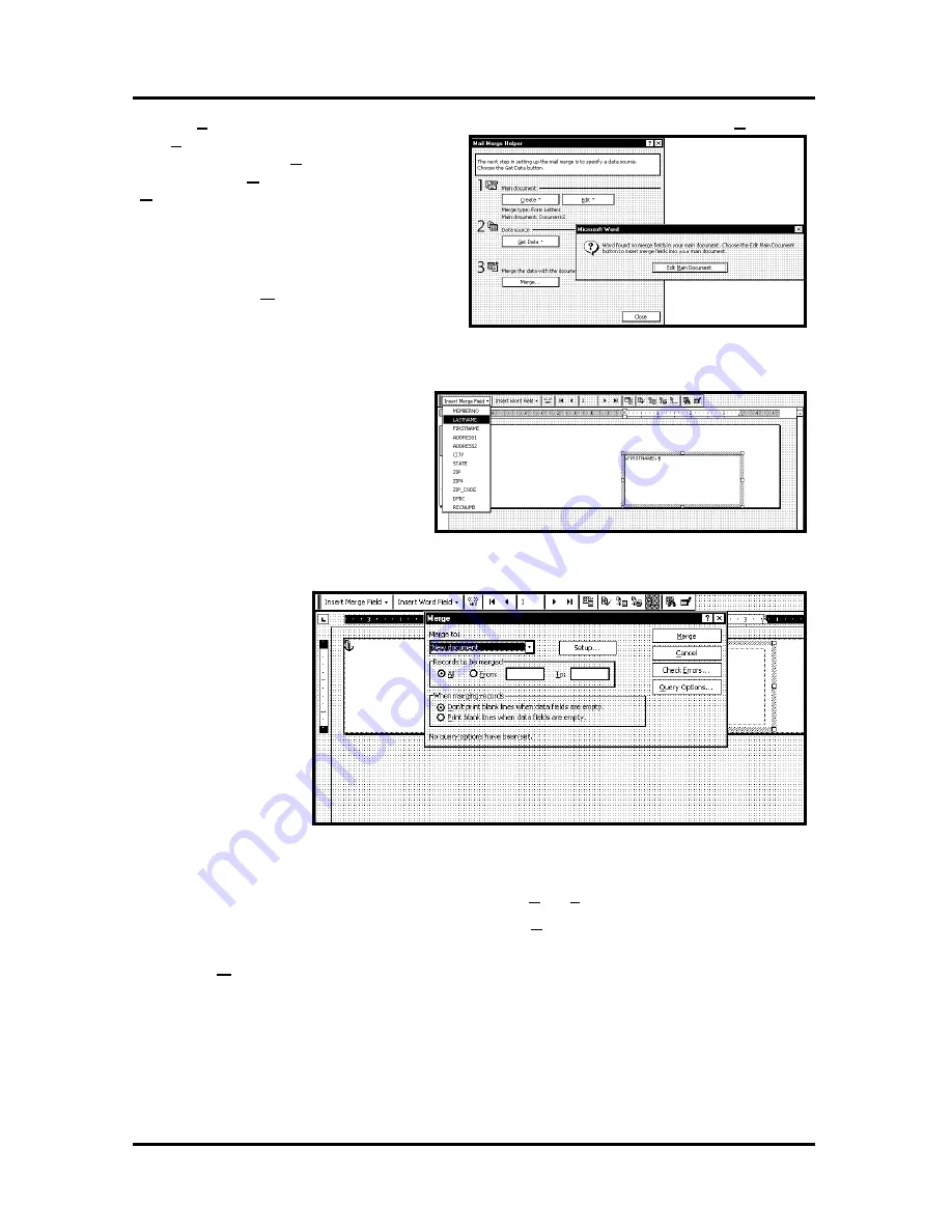
Next click on
Edit Main Document
and then
click on
Close
.
Use the Mail Merge Tool Bar and click on
Insert Merge Field and begin to build the
layout by inserting the address fields.
When you have
completed setting up the
layout, click on the
Merge
icon on the tool
bar and the “Merge”
window will open.
In the
Merge to
menu
there are several choices
for where how the data is
exported. The two that
concerns us is “New
Document” and
“Printer”. If you choose
“New Document” the
merge will be created in your word application with a separate record for each address. If you choose
“Printer”, the merge will send directly to the printer and each record will be printed.
The next selection is “Records to be merged”. You can select
All
or
From
:.
The last selection is “When merging records”. The default is “Don’t print blank lines when data fields are
empty.” This should be left checked.
Clicking on
Merg
e will start the process of merging the documents.
If you chose to send the merge directly to the printer and the printer is connected to the computer and
turned ON, the printer will start. Pressing the
ENTER
key will start the printing process.
If you have a graphic or fixed text to be printed with the data, refer to the section on Overlays.
© 2009 Neopost USA Inc. All rights reserved.
35
Summary of Contents for AS-940
Page 1: ...AS 940 Addressing Solution Operating Guide...
Page 12: ...SECTION 1 GETTING ACQUAINTED Notes 2009 Neopost USA Inc All rights reserved 12...
Page 36: ...SECTION 3 OPERATING THE PRINTER Notes 2009 Neopost USA Inc All rights reserved 36...
Page 42: ...Notes 2009 Neopost USA Inc All rights reserved 42...


