background image

Xn120 System 


Xn120 Getting Started Guide 


     3 

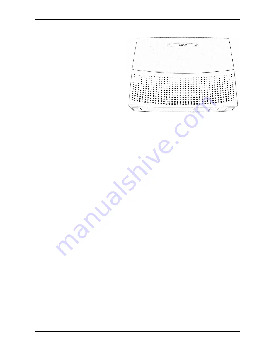
What is the Xn120? 

 
The Xn120 system consists of a main unit with 
a base board pre-installed. 
The Xn120 telephone system will allow the 
connection of up to three exchange lines plus 
eight telephones. The eight telephones can be 
either Xn120 system telephones or normal 
telephones. 
The Xn120 can have an external music source 
connected that can be played to callers placed 
on hold. 
There is also a connection for an external 
paging system.


It can also accommodate optional parts to 
expand the system or connect ISDN BRI lines.  
Further more, there are optional expansion 
units available to increase the number of exchange lines and telephones that can be connected. Separate 
guides are supplied with the optional equipment. 
 
All equipment will operate when the Xn120 is installed as shown in this guide, it is not necessary to make any 
changes to the system configuration. 
With the default settings: 

· 

Each telephone will function and is assigned an extension number. 

· 

Calls received on the exchange lines will ring at telephone number 200.  

· 

Each telephone can make outside calls by dialing 9. 

· 

Each exchange line is presented at a Function Key with busy lamp indication. 


Outside lines 

You can connect up to three analogue exchanges lines to the Xn120.  

· 

The exchange lines must be loop start type.  

· 

The Xn120 will also detect Caller ID sent by the Network Provider. The Caller ID must be the ring alert type 
with FSK signaling. 

· 

Each line is connected via an RJ11 6/4 way socket. Three cables are supplied with the Xn120 to connect to 
the exchange lines supplied by your Network Provider. 


Summary of Contents for XN120 Vision

Page 1: ...that you have purchased Please keep all information supplied for future reference Regulatory Notice Refer to the Declaration of Conformity related to the product at the end of this document Warning Th...

Page 2: ...Ringing Assignment 25 Example Configuration 28 Telephone Ringing Style 29 Internal Call Ringing Mode 29 Outgoing Exchange Line Access 30 Caller ID 32 Recall for Normal Telephones 34 Department Groups...

Page 3: ...eparate guides are supplied with the optional equipment All equipment will operate when the Xn120 is installed as shown in this guide it is not necessary to make any changes to the system configuratio...

Page 4: ...ur own requirements The Xn120 system telephones with an LCD display will show information about who is calling you the call you are on or the feature you are using Each telephone is connected to the X...

Page 5: ...Card For adding expansion cabinets Call Logging Ethernet connection and CF card slot Installed onto the main board in the Xn120 unit 20OPBOX For ISDN BRI cards 2 slots available per unit Plugs onto th...

Page 6: ...er installation considerations in section 3 If you have any optional parts to install please check any installation considerations in the documentation supplied with each item 4 Connect the telephones...

Page 7: ...al Items Required Cross head screwdriver 4 Wall fixing plugs suitable for the type of wall Solid wire for extending telephone cabling Recommended cable type Twisted pair CW1308 or similar specificatio...

Page 8: ...reason you have problems installing the Xn120 you will need your old system in working order to continue your business If you plan to use existing telephone cabling within your building check o The ca...

Page 9: ...emit high frequency radiation Near computers microwaves air conditioners etc Near radio antennas including shortwave If you are installing the optional expansion box or expansion cabinets ensure there...

Page 10: ...quires disconnection then the telecommunication network connection s CO and or ISDN must be disconnected first from the Xn120 Important The system must have a permanent Earth Ground connection to a ve...

Page 11: ...e Xn120 unit OR Use the RJ11 to bared wire cables supplied with the Xn120 and RJ11 sockets Connections Xn120 ST socket RJ11 socket Pin 2 black Pin 2 Pin 3 red Pin 3 Pin 4 green Pin 4 Pin 5 yellow Pin...

Page 12: ...et Pin 2 black White green Pin 3 red Blue white Pin 4 green White blue Pin 5 yellow Green white The connections are polarity sensitive you must connect as shown Ensure that you use a separate twisted...

Page 13: ...are not polarity sensitive Ensure that you use a twisted pair for the speech Pins 3 4 speech This will ensure that you can reach the maximum cable length of 1125 metres Identify each line jack unit w...

Page 14: ...cable protectors if the cables are run on the floor Aerial distribution wiring is not allowed Use lightning protectors for each exchange line Use the cables supplied with the Xn120 The exchange line...

Page 15: ...b cover to the right of the ST1 ST8 sockets An RJ11 cable is supplied with the system The external music device is not supplied with the Xn120 The connections of the RJ11 plug supplied with the Xn120...

Page 16: ...b cover to the right of the ST1 ST8 sockets An RJ11 cable is supplied with the system The external paging system is not supplied with the Xn120 The connections of the RJ11 plug supplied with the Xn120...

Page 17: ...tion The NORMAL switch is located under the sub cover on the right side of the ST1 ST8 connection sockets 2 Switch ON the power at the source Switch ON the power switch on the left side of the Xn120 u...

Page 18: ...left side of the Xn120 unit System Start Up Retain Customer Configuration This is the normal operation for powering the Xn120 on Before you power on the system check that the NORMAL switch is set to...

Page 19: ...you do not hear dialing tone move to step 2 2 Check the connections Check the connections from the phone to the Xn120 ensure both wires are connected as shown in 4 Connect the Telephones on page 11 3...

Page 20: ...m the exchange line to the Xn120 ensure both wires are connected to CO2 as shown in 5 Connect the Exchange Lines on page 14 4 To test CO3 At a Xn120 system phone lift the handset and dial 805 03 If yo...

Page 21: ...entering the previous values Do not unplug the phone If it is unplugged by mistake then plug it back in wait for the display to show time and date and then press HOLD to return to the configuration mo...

Page 22: ...tem phone to select the program item and change its value etc The LCD display will show the current program item the editing point is shown by a flashing curser SPK Save changes and exit configuration...

Page 23: ...step on to the next if you did not make any changes to the entry Exiting Configuration Mode When you exit configuration mode your changes will be saved into the battery backed memory Until you exit a...

Page 24: ...tep to the next option Enter one digit for the day of the week 1 7 1 Sunday 2 Monday 3 Tuesday etc Press HOLD to confirm the entry and step to the next option Enter the two digits for the hour 24h for...

Page 25: ...lephone simply press the key that corresponds to the mode you require 1 Program 22 05 01 The Incoming Ring Group IRG number is assigned to the exchange lines Different IRG s can be assigned to each ex...

Page 26: ...nished 4 Assign a key to each mode Choose a telephone that will be able to change the day night mode Exit Configuration Mode The keys are set at the telephone itself not within Xn120 configuration mod...

Page 27: ...Trunk 1 Prg 22 05 01 default IRG1 Trunk 2 Prg 22 05 01 default IRG1 Trunk 3 Prg 22 05 01 default IRG1 1 2 3 4 5 6 7 8 Turn on the ability to change the mode Mode Change Setting Default 0 off 20 07 01...

Page 28: ...dedicated line and should go to telephone 206 at all times Telephone 200 will have Function keys to change the mode for day lunch etc Step 1 Place the telephones into an IRG for each of the modes day...

Page 29: ...to 8 Press HOLD to step to the next item Enter the ring pattern for internal calls 3 is a single ring 8 is a double ring Press HOLD to confirm the entry and step to the next option Press DC several t...

Page 30: ...to return to the Program Mode Press SPK to save changes and exit if you are finished 2 Program 14 07 01 Give each exchange line the access properties for the TAM number Default Setting Each exchange...

Page 31: ...e 51 TAM numbers available Give each exchange line the access properties for the TAM number Prg 14 07 01 TAM Number Trunk 1 Trunk 2 Trunk 3 1 7 7 7 2 0 0 0 3 0 0 0 4 0 0 0 5 0 0 0 Values available 0 N...

Page 32: ...to turn on Caller ID you can overwrite the current entry Press HOLD to confirm the entry and step to the next option Press DC several times when you are done to return to the Program Mode Press SPK to...

Page 33: ...eet Caller ID With defaults shown Turn on the Caller ID for each trunk Prg 14 02 10 Trunk number Setting Default 0 Off Trunk 1 Trunk 2 Trunk 3 Turn on the Caller ID for each normal telephone Prg 15 03...

Page 34: ...n this program 82 04 04 13 82 04 07 14 82 04 08 25 Default Setting The Xn120 will accept a RECALL duration of 105mS to 1000mS Change the setting to 13 this is equivalent to 65mS Press HOLD 3 times to...

Page 35: ...ot answered stay at the last member or keep trying each member How long each member rings before the call will step on to the next one available Program 16 02 01 Place the telephones into a department...

Page 36: ...phones Press HOLD to confirm the entry and step to the next option Press DC several times when you are done to return to the Program Mode Press SPK to save changes and exit if you are finished Program...

Page 37: ...a new number Press DC several times when you are done to return to the Program Mode Press SPK to save changes and exit if you are finished See Also There are no related settings Configuration Sheet De...

Page 38: ...datory you can leave this set to 0 Default Setting None of the telephones are in a paging group For each telephone enter the paging group number 0 32 enter 0 to remove the phone from a group you can o...

Page 39: ...external music device Program 10 04 01 Select the device used for the music on hold tune Default Setting The Xn120 s own tune is played to callers placed on hold Enter 1 to select the external device...

Page 40: ...ine socket If your exchange lines are provided with a normal telephone socket you can unplug the Xn120 connection and plug a normal telephone into the socket to make receive calls You can plug a phone...

Page 41: ...ephone You can not use a Xn120 system phone in socket ST8 with the power fail link set to PF When Power Fail is set to OFF marked KT on the card When the power fails or the Xn120 is switched off Excha...

Page 42: ...e by simply going off hook and dialing its number The default telephone numbers are 200 to 207 If you have a Xn120 system phone with an LCD display your telephone number will be displayed at the lower...

Page 43: ...ng the number you require If you have a Xn120 system phone you can also seize the line by pressing an idle line key The line is idle when the lamp is off Placing a Call on HOLD While you are on a call...

Page 44: ...all it will ring you back after 30 seconds Or b Wait for your co worker to answer and announce that you have a call for them then press the TRFR key or go on hook to transfer the call through HOLD and...

Page 45: ...ng You have place the line on hold Press the key to retrieve the held call Red Another telephone is using the line Red flashing Another telephone has placed the line on hold Press the key to retrieve...

Page 46: ...below for each function key type Example SPK 851 Press Key 1 See below for each function key type The current setting of the function key will be displayed 01 for a DSS key Enter the telephone number...

Page 47: ...r a Page zone key Enter the zone number 1 9 Press SPK to end Or another function key if you have more to set 21 1 SPK You will hear a short confirmation tone If you hear a long reject tone the key has...

Page 48: ...e number of the telephone you want to name Enter the new name using the characters above the keypad as a guide Press to move to the next character Press to insert a space Press HOLD to confirm the new...

Page 49: ...l Forwarding when Not Answered Calls forward when your extension is not answered 848 Call Forwarding Immediate All calls forward immediately to the destination and only the destination rings Setting C...

Page 50: ...call ringing this phone Any Call Pickup You are not certain which telephone is ringing you want to pickup the call whichever phone is ringing Direct Call Pickup Lift the handset Dial Service Code 715...

Page 51: ...side calls 2 Blocks Paging Intercom calls Call Forwards and transferred outside calls 3 Blocks all calls 4 Blocks Call Forwards 0 Cancels Do Not Disturb Setting Do Not Disturb Press SPK Dial Service C...

Page 52: ...guration section You can als make a paging call over external speakers if you have connected the Xn120 to an external paging amplifier see Paging External Making an All Call Page Lift the handset Dial...

Page 53: ...al paging amplifier before you can use this feature see Connecting External Paging Amplifiers in the Installation section Making an External Page Call Lift the handset Dial Service Code 803 for paging...

Page 54: ...The date can only be changed within the Xn120 Configuration Mode Setting the System Time Press SPK Dial Service Code 828 for setting the system time Enter the new time in 24Hour format hh mm Press SPK...

Page 55: ...the Phone Book Press SPK Dial Service Code 853 to add a new number Enter the location you want to add 000 999 Enter the outside number You do not need to include the trunk access code Press HOLD to co...

Page 56: ...dialled number will not be displayed if it is more than 8 digits long To Access the Other Features The features of the Xn120 are accessed by dialing the Service Code each feature has its own code If y...

Page 57: ...o 9 and by sending a tone each time a button is pressed FSK Frequency Shift Keying A method of sending data by changing the frequency LCD Liquid Crystal Display LJU Line Jack Unit used to connect norm...

Page 58: ...Declaration of Conformity 58 Xn120 Getting Started Guide Declaration of Conformity...

Page 59: ...Declaration of Conformity Xn120 Getting Started Guide 59...

Reviews: