background image


Please read this manual carefully before installing this product and save this manual for future use. 
 
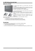
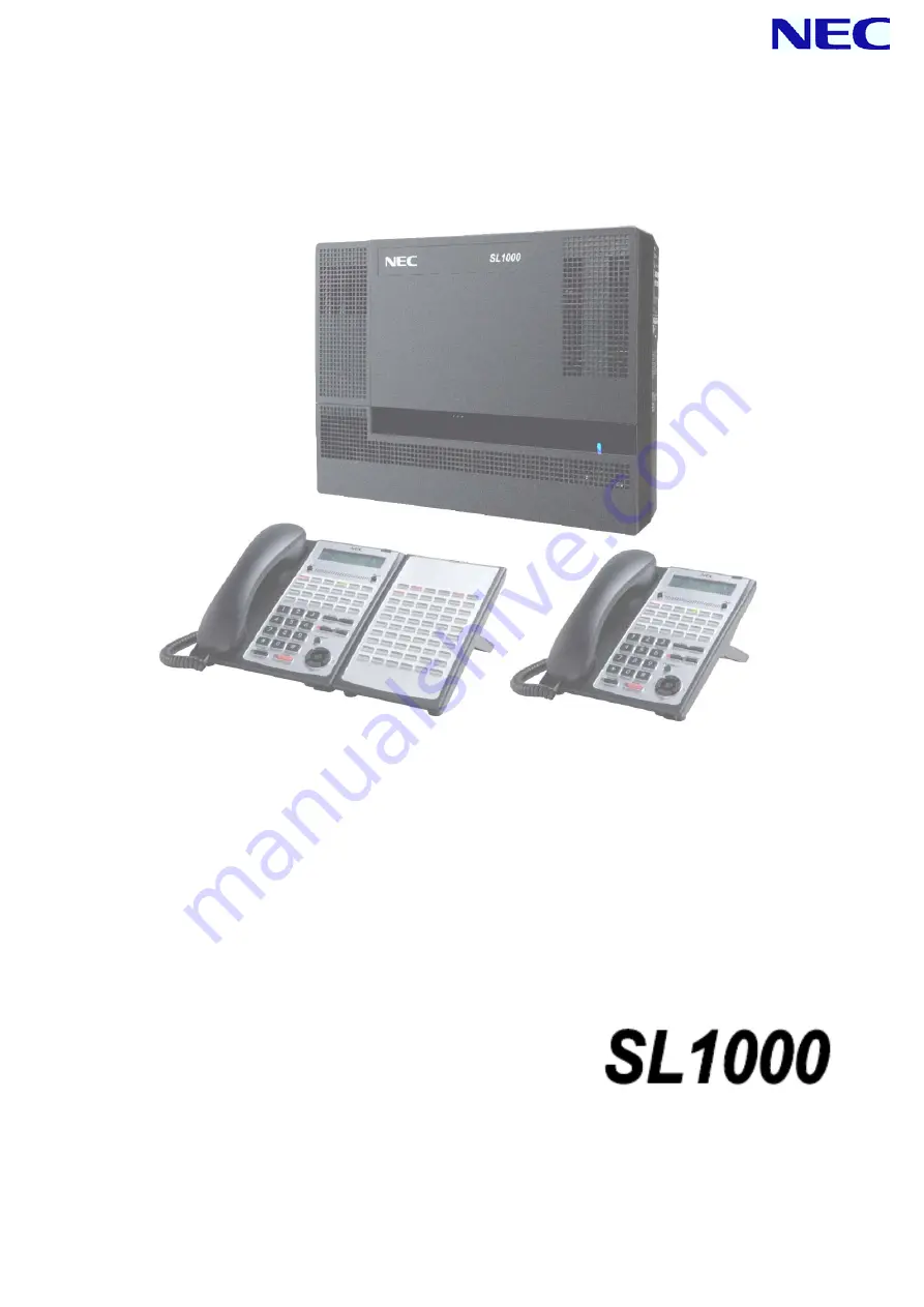
This guide explains the installation, configuration and operation of the SL1000 Telephone System including 
the Outside (CO) line and telephone connections. 
This Getting Started Guide will cover the most frequently used configuration options. Only the SL1000 Main 
KSU is included, it does not cover optional items. 
For more advanced configuration, refer to Hardware Manual (separate issue) for the details.


(IP4WW-1632M-A KSU) 

Getting Started Guide

Issue 1.0 (January. 2011)


A50-031579-001 

Summary of Contents for SL1000

Page 1: ...ne System including the Outside CO line and telephone connections This Getting Started Guide will cover the most frequently used configuration options Only the SL1000 Main KSU is included it does not...

Page 2: ...LINE TELEPHONES TEST EACH PHONE IN TURN 22 2 TEST THE ANALOG TELEPHONES TEST EACH PHONE IN TURN 22 3 TEST THE OUTSIDE CO LINES TEST EACH LINE IN TURN 23 INSTALL OPTIONAL UNITS AND EQUIPMENTS 23 POWER...

Page 3: ...SED TO DISCONNECT THE MAIN POWER ENSURE THAT THE AC OUTLET IS LOCATED NEAR THE EQUIPMENT AND IS EASILY ACCESSIBLE DISCONNECT ALL POWER TO THE EQUIPMENT BEFORE COVER S ARE REMOVED DO NOT TOUCH THE INTE...

Page 4: ...IN NEC DESIGNATED COUNTRIES IF THE SYSTEM REQUIRES INSTALLATION OR REPAIR CONTACT THE DEALER OR ITS SERVICE TECHNICIAN FOR THE PERIODIC REPLACEMENT PARTS OR OPTION PRODUCTS PLEASE ASK YOUR SUPPLIER B...

Page 5: ...may be where the batteries were originally sold or a local seller of automotive batteries Contact your local waste management officials for other information regarding the environmentally sound colle...

Page 6: ...into the municipal waste stream This contributes to the protection of human health and the environment Please be informed that a fine may be imposed for illegal disposal of electrical and electronic...

Page 7: ...be connected All equipment will operate when the SL1000 is installed as shown in this guide it is not necessary to make any changes to the system configuration Calls received on the exchange lines wil...

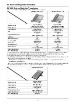
Page 8: ...SL1000 system Multi line telephones to any of the station connections If you need more telephones you will need to install optional cards The SL1000 system Multi line telephones have illuminated func...

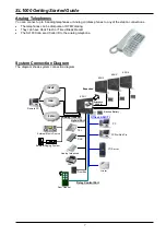
Page 9: ...med Break Recall The SL1000 can send Caller ID to the analog telephone System Connection Diagram The diagram shows system connection diagram P PS ST TN N IP VoIP ISDN DSS Analog Telephone FAX DoorBox...

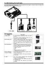
Page 10: ...ected to the power supply for each KSU The battery itself must be prepared by local supplier IP4WW MEMDB C1 This card provides additional expansion memory Interface Install onto the CPU card MEMDB slo...

Page 11: ...he SL1000 Main KSU CAT5 connection cable is supplied with the SL1000 Expansion KSU IP4WW CFVRS C1 Compact Flash card for VRS 512MB Compact Flash card mounted onto the PZ VM21 card within the SL1000 Ma...

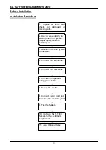
Page 12: ...ing telephone system Aspila Topaz Xn120 or IPC100 3 Mount the SL1000 system on the wall 4 Connect the Telephones 5 Connect the Trunk Lines 8 Connect the AC Cord and Switch on the SL1000 system 9 Test...

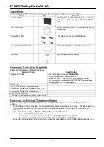
Page 13: ...eters Analog Telephone 1125 meters RJ11 Plugs Fixing Tools for RJ11 Plug and cable 2 conductor connectors for outside CO line 4 conductor connectors for extension Cross head screwdriver 4 Wall Fixing...

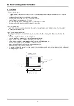
Page 14: ...vironmental standards maximizes the life of the system Make sure that the site is not In direct sunlight or in hot cold or humid places In dusty areas or in areas where sulfuric gases are produced In...

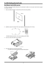
Page 15: ...1 Place the attached template on the wall to mark the four screw positions 2 Install four screws into the wall The screw heads must protrude about 2 5 to 3 5 mm Wall Mounting Screws M4 1x 25 4 pcs ar...

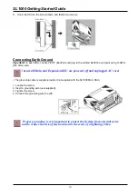
Page 16: ...Ensure all Main and Expansion KSU are powered off and unplugged AC cord The grounding cable is supplier provided not supplied with the SL1000 Main KSU 1 Loosen the screw 2 Insert a grounding wire use...

Page 17: ...ST8 can be used to provide a working telephone should the power be disconnected from theSL1000 1 Insert the modular plugs of the extension line cords 2 wire 4 wire into the extension modular jacks on...

Page 18: ...ition Setting 1 Turn telephone over button side down 2 Adjust the Legs to desired height 3 Lead the Line and Handset cords through the applicable grooves 4 Turn telephone over button side up 2 High Po...

Page 19: ...e 1 Arrange the cables and put down the leg as shown below 2 Remove the hook switch hanger and Insert the hook switch hanger in the slot below the hook switch 3 Install 2 screws into a wall The screw...

Page 20: ...will need this when you configure the SL1000 System SL1000 system CO number Outside CO line dialing number e g 03 5217 9493 CO1 CO2 CO3 CO4 Check Power Fail Operation later in this guide CO1 can be us...

Page 21: ...s 1 Depending on the cabling select either Right route or Left route for the cabling Clamp and route the cable to outside 2 Cut and remove desired plastic filter piece s at the Sub Cover for cables 3...

Page 22: ...l PCBs are configured equipped and strapped correctly AC power cord is cabled correctly At least one Display type Multi Line Telephone is connected to the system for Programming Pull out the Lithium B...

Page 23: ...emory 1 Set the power switch is OFF position 2 Open the Sub Cover of the SL1000 main KSU and make sure the Load button S1 location on the CPU card 3 Connect the AC power cord to the KSU then plug the...

Page 24: ...the ST connection at the SL1000 unit If you have used telephone cable and RJ11 sockets to extend the connections Plug the phone directly into the ST connection at the SL1000 unit using the line cord s...

Page 25: ...ialing tone check the connections from the Outside CO line to the SL1000 ensure both wires are connected to CO2 as shown in on page 18 4 To test CO3 At a SL1000 Multi Line Telephone lift the handset a...

Page 26: ...connected to the specified extension port Trunk Port No 1 Extension Port No 8 The connected extension must be SLT Single Line Telephone Hardware switch J6 must be set from KT to PF side default KT whe...

Page 27: ...Analog telephone into the socket to make receive calls You can plug a phone in each Outside CO line socket if you wish 3 Use the External Backup Battery Box Option to connect each KSU The external bac...

Page 28: ...onsists of exchange lines and telephones connected to the 008 408 cards you have installed Within the SL1000 configuration the Outside CO lines are referred to as trunks and the telephones as extensio...

Page 29: ...uration setting within the SL1000 is identified by a Program Number eg 22 05 01 Operation Display shows 1 Ensure the LCD Display shows If it is not displayed press the Mute key several times to step b...

Page 30: ...ng with 1 Pressing Mute one last time brings you to the beginning program display allowing you to enter any program number DND CONF Switch between the different input data fields by pressing DND CONF...

Page 31: ...ption 8 Enter the two digits of the seconds 00 59 Press Hold key to confirm the entry and step to the next option 9 Press Mute key several times when you are done to return to the Program Mode 10 Pres...

Page 32: ...Mute key several times when you are done to return to the Program Mode 7 Press Speaker key to save changes and exit from the Programming Mode Program22 04 01 The telephones are placed into Ring Group...

Page 33: ...re set at the telephone itself not within SL1000 Programming Mode Default Setting There are no keys set to day night modes on any of the telephones Operation Display shows 1 At the telephone that you...

Page 34: ...5 01 default IRG1 Trunk 4 PRG 22 05 01 default IRG1 1 2 3 4 5 6 7 8 Turn on the ability to change the mode Mode Change Setting Default 0 off PRG20 07 01 Assign Keys at the telephone s that will change...

Page 35: ...each of the modes day time lunch time evenings and weekends IRG Number List of telephones that will ring PRG 22 04 01 IRG 1 200 202 day time IRG 2 205 lunch time IRG 3 207 evenings and weekends IRG 4...

Page 36: ...Off 2 0 4 On 0 5 Off 0 5 5 On 0 25 Off 0 25 6 On 0 5 Off 0 5 On 0 5 Off 1 5 7 On 0 25 Off 0 25 On 0 25 Off 5 25 8 On 0 375 Off 0 25 On 0 375 Off 2 0 9 On 0 25 Off 0 125 On 0 25 Off 0 125 On 0 25 Off 2...

Page 37: ...Internal calls Operation Display shows 1 After Log In to the Programming Mode If you already Log In the programming mode skip this operation 2 Dial 20 02 12 Change the Internal Call Ringing Mode 0 Rin...

Page 38: ...ee Changing the Telephone Ringing Assignment for the modes you may be using Default Setting All telephones have TAM number 1 Operation Display shows 1 After Log In to the Programming Mode If you alrea...

Page 39: ...hed See Also Changing the Telephone Ringing Assignment Configuration Sheet Outgoing Exchange Line Access With defaults shown Give each telephone a TAM number PRG 15 06 01 TAM Number for each day night...

Page 40: ...the programming mode skip this operation 2 Dial 14 02 10 For each trunk enter 1 to turn on Caller ID you can overwrite the current entry and Press Hold key to confirm the entry and step to the next op...

Page 41: ...Operation Display shows 1 After Log In to the Programming Mode If you already Log In the programming mode skip this operation 2 Dial 82 04 04 Enter the Maximum Break Time default 100ms 20 and Press H...

Page 42: ...gramming mode skip this operation 2 Dial 16 02 01 For each telephone enter the Group number 1 32 that is a member of you can overwrite the current entry and Press Hold key to confirm the entry and ste...

Page 43: ...Mode 5 Press Speaker key to save changes and exit if you are finished Program16 01 09 Select how long calls ring at each member of the department group You can use this option to turn off the step on...

Page 44: ...when you are done to return to the Program Mode 4 Press Speaker key to save changes and exit if you are finished See Also There are no related settings Configuration Sheet Department Groups With defa...

Page 45: ...to the Programming Mode If you already Log In the programming mode skip this operation 2 Dial 31 02 01 For each telephone enter the paging group number 0 32 enter 0 to remove the phone from a group y...

Page 46: ...tice NEC Corporation has prepared this document for use by its employees and customers The information contained herein is the property of NEC Corporation and shall not be reproduced without prior wri...

Reviews: