


A-2 Connector Pin Assignments
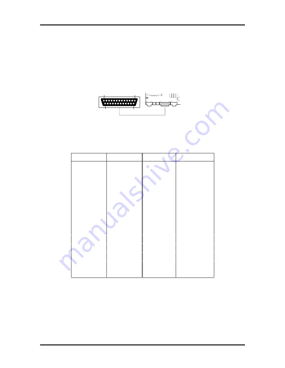
PARALLEL INTERFACE CONNECTOR
Figure A-1 Parallel Interface Connector
Table A-2 Parallel Interface Pin Assignments
Pin
Signal Name
Pin
Signal Name
1
Strobe
14
Auto Feed
2
Data Bit 0
15
Fault
3
Data Bit 1
16
INIT
4
Data Bit 2
17
SLCT IN
5
Data Bit 3
18
Ground
6
Data Bit 4
19
Ground
7
Data Bit 5
20
Ground
8
Data Bit 6
21
Ground
9
Data Bit 7
22
Ground
10
ACK
23
Ground
11
BUSY
24
Ground
12
ERROR
25
Ground
13
SLCT
The following figure shows the parallel interface connector on the system board. Table A-2
provides the pin assignments.
13
1
25
14
Summary of Contents for POWERMATE PRO150
Page 152: ...A 16 Connector Pin Assignments ...
Page 160: ...B 8 System Board Settings ...