8-3
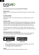
DISASSEMBLY
CABINET ASSY
24DT6761
A14
PL-CPIMSx4x14x3KF
910E4046
A38
ELECTRICAL TAPE
92203970
A49
FLAT CABLE 80P-L80
73499359
A46
PL-CPIMSx4x14x3KF
910E4046
A38
GRAND BOARD R
24H32091
A45
FILTER
24K23941
A48
GRAND BOARD L
24H32081
A45
VOL PWB
933T7MC1
A03
CBIPSx3x8x3KF
24N03691
A36
PL-CPIMSx3x12x3KF
910E3071
A39
BRACKET (PS) L
24F28821
A31
CLAMPER (D13, V-2)
24280931
A32
CBIPS
x4x12x3KF
24N03711
A34
CBIPSx4x12x3KF
24N03711
A34
BRACKET (MDL)
24H30051
A30
CBIPSx3x8x3KF
24N03691
A36
PL-CPIMSx3x12x3KF
910E3071
A39
POWER PWB
933T7MG1
A07
BRACKET (PS) R
24F28831
A29
PL-CPIMSx4x14x3KF
910E4046
A38
CTL PWB
933T7MH1
A06
BUTTON (PWR)
24G04911
A42
PL-CPIMSx4x8x15BF
910E4011
A40
PL-CPIMSx4x8x15BF
910E4011
A40
POWER UNIT
79645761
A41
a
a
d
CBIPSx3x8x3KF
24N03691
(2 pcs.) (Marked by b)
A36
PL-CPIMSx4x14x3KF
910E4046
A38
SUPPORT POST
(WSK-314)
24C03851
A43
CBIPSx3x8x3KF
24N03691
A36
PL-CPIMSx3x8x15KF
910E3053
A35
PL-CPIMSx3x12x15KF
910E3071 (10 pcs.) (Marked by d)
A39
SHIELD PLATE (L)
24H29231
A25
b
a
a
d
b
b
b
b
b
a
a
d
d
d
CBIPSx3x12x3KF
24N03711
(8
pcs.) (Marked by a)
A34
SHIELD PLATE (R)
24H29242
A25
d
d
d
b
b
b
a
a
b
b
b
d
PL-CPIMSx3x8x15KF
910E3053
A35
d
Summary of Contents for PlasmaSync PX-42M2A
Page 8: ...3 1 USERS MANUAL ...
Page 9: ...3 2 USERS MANUAL ...
Page 10: ...3 3 USERS MANUAL ...
Page 11: ...3 4 USERS MANUAL ...
Page 12: ...3 5 USERS MANUAL ...
Page 13: ...3 6 USERS MANUAL ...
Page 14: ...3 7 USERS MANUAL ...
Page 15: ...3 8 USERS MANUAL ...
Page 16: ...3 9 USERS MANUAL ...
Page 17: ...3 10 USERS MANUAL ...
Page 18: ...3 11 USERS MANUAL ...
Page 19: ...3 12 USERS MANUAL ...
Page 20: ...3 13 USERS MANUAL ...
Page 21: ...3 14 USERS MANUAL ...
Page 22: ...3 15 USERS MANUAL ...
Page 23: ...3 16 USERS MANUAL ...
Page 24: ...3 17 USERS MANUAL ...
Page 25: ...3 18 USERS MANUAL ...
Page 26: ...3 19 USERS MANUAL ...
Page 27: ...3 20 USERS MANUAL ...
Page 28: ...3 21 USERS MANUAL ...
Page 29: ...3 22 USERS MANUAL ...
Page 30: ...3 23 USERS MANUAL ...
Page 31: ...3 24 USERS MANUAL ...
Page 32: ...3 25 USERS MANUAL ...
Page 33: ...3 26 USERS MANUAL ...
Page 34: ...3 27 USERS MANUAL ...
Page 35: ...3 28 USERS MANUAL ...
Page 36: ...3 29 USERS MANUAL ...
Page 37: ...3 30 USERS MANUAL ...
Page 38: ...3 31 USERS MANUAL ...
Page 39: ...3 32 USERS MANUAL ...
Page 40: ...3 33 USERS MANUAL ...
Page 41: ...3 34 USERS MANUAL ...
Page 42: ...3 35 USERS MANUAL ...
Page 43: ...3 36 USERS MANUAL ...
Page 44: ...3 37 USERS MANUAL ...
Page 45: ...3 38 USERS MANUAL ...
Page 46: ...3 39 USERS MANUAL ...
Page 47: ...3 40 USERS MANUAL ...
Page 48: ...3 41 USERS MANUAL ...
Page 49: ...3 42 USERS MANUAL ...
Page 50: ...3 43 USERS MANUAL ...
Page 51: ...3 44 USERS MANUAL ...
Page 52: ...3 45 USERS MANUAL ...
Page 53: ...3 46 USERS MANUAL ...
Page 54: ...3 47 USERS MANUAL ...
Page 55: ...3 48 USERS MANUAL ...
Page 56: ...3 49 USERS MANUAL ...
Page 57: ...3 50 USERS MANUAL ...
Page 58: ...3 51 USERS MANUAL ...
Page 59: ...3 52 USERS MANUAL ...
Page 60: ...3 53 USERS MANUAL ...
Page 61: ...3 54 USERS MANUAL ...
Page 62: ...3 55 USERS MANUAL ...
Page 63: ...3 56 USERS MANUAL ...
Page 64: ...3 57 USERS MANUAL ...
Page 65: ...3 58 USERS MANUAL ...
Page 66: ...3 59 USERS MANUAL ...
Page 67: ...3 60 USERS MANUAL ...
Page 68: ...3 61 USERS MANUAL ...
Page 69: ...3 62 USERS MANUAL ...
Page 70: ...3 63 USERS MANUAL ...
Page 71: ...3 64 USERS MANUAL ...
Page 72: ...3 65 USERS MANUAL ...
Page 73: ...3 66 USERS MANUAL ...
Page 74: ...3 67 USERS MANUAL ...
Page 75: ...3 68 USERS MANUAL ...
Page 76: ...3 69 USERS MANUAL ...
Page 77: ...3 70 USERS MANUAL ...
Page 78: ...3 71 USERS MANUAL ...
Page 79: ...3 72 USERS MANUAL ...
Page 80: ...3 73 USERS MANUAL ...
Page 81: ...3 74 USERS MANUAL ...
Page 82: ...3 75 USERS MANUAL ...
Page 135: ...METHOD OF DISASSEMBLY 7 1 1 Diagonal view of the unit front ...
Page 136: ...2 Diagonal view of the unit rear 7 2 METHOD OF DISASSEMBLY ...
Page 148: ...MEMO ...
Page 152: ...MEMO ...
Page 155: ...B SAFETY BRACKET SASSY C CAP SASSY D SERVICE BAG SASSY PACKAGING 10 2 ...
Page 157: ...PACKAGING 10 4 G CUSHION CARTON BOX ...
Page 159: ...Outer box PACKAGING 10 6 ...
Page 162: ...2 PX42M2G ...
Page 163: ...12 1 CONNECTION DIAGRAMS ...
Page 164: ...13 1 BLOCK DIAGRAMS I O ANALOG ...
Page 165: ...13 2 BLOCK DIAGRAMS VIDEO AUDIO ...
Page 166: ...13 3 BLOCK DIAGRAMS POWER UNIT ...
Page 168: ...I O PWB PWC 4213B PARTS SIDE SOLDER SIDE SCHEMATIC DIAGRAMS 14 2 ...
Page 179: ...ANALOG PWB PWC 4214 PARTS SIDE SCHEMATIC DIAGRAMS 14 13 ...
Page 180: ...ANALOG PWB PWC 4214 SOLDER SIDE SCHEMATIC DIAGRAMS 14 14 ...
Page 184: ...VIDEO PWB PWC 4213A PART SIDE SCHEMATIC DIAGRAMS 14 18 ...
Page 185: ...VIDEO PWB PWC 4213A SOLDER SIDE SCHEMATIC DIAGRAMS 14 19 ...
Page 187: ...AUDIO PWB PWC 4216A PARTS SIDE SCHEMATIC DIAGRAMS 14 21 ...
Page 188: ...AUDIO PWB PWC 4216A SOLDER SIDE SCHEMATIC DIAGRAMS 14 22 ...
Page 190: ...SOUND I O PWB PWC 4216B PART SIDE SOLDER SIDE SCHEMATIC DIAGRAMS 14 24 ...
Page 196: ...MEMO ...
Page 197: ...PRINTED IN JAPAN 9806MI1250 01272002 PX 42M2A 01272003 PX 42M2G ...