background image

AD-25182501

CHAPTER 3

Page 23

Revision 1.0.1

NAP- 200-003
Sheet  5/29
Installation of Main Equipment

(4)

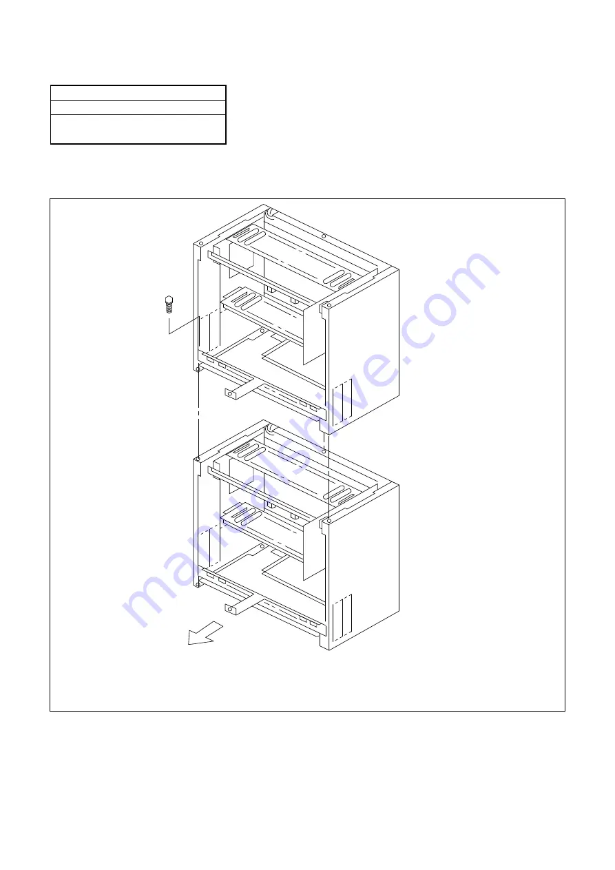
When the system is a multiple-PIM configuration, connect PIMs to each other as shown in Figure 003-5,
using the 3 hex-bolts supplied.

Figure 003-5  Connection of PIMs

Note 1 :

The BATTM and/or the MDFM can be installed the same as the PIM.

Note 2 :

For simplicity, the BASE and RACK PARTS are not shown.

PIM 

Note

PIM   

Note

FRONT

Summary of Contents for NEAX 7400 ICS

Page 1: ...AD 25182501 ISSUE 1 0 1 Model 120 Installation Procedure Manual OCTOBER 1995 NEC Australia Pty Ltd...

Page 2: ...me without notice NEC Australia Pty Ltd has prepared this document for use by its employees and customers The information contained herein is the property of NEC Australia Pty Ltd and shall not be rep...

Page 3: ...N0 8 7 6 5 4 3 2 1 0 1 1 0 1 1 0 1 1 0 1 1 0 1 1 0 1 1 0 1 1 0 1 1 0 1 1 0 1 1 0 1 1 0 1 1 0 1 1 0 1 1 0 1 ISSUE No 9 10 11 12 13 14 15 16 17 18 19 20 21 22 PAGE N0 8 7 6 5 4 3 2 1 0 1 1 0 1 1 0 1 1 0...

Page 4: ...8 7 6 5 4 3 2 1 0 1 1 0 1 1 0 1 1 0 1 1 0 1 1 0 1 1 0 1 1 0 1 1 0 1 1 0 1 1 0 1 1 0 1 1 0 1 1 0 1 1 0 1 ISSUE No 65 66 67 68 69 70 71 72 73 74 75 76 77 78 PAGE N0 8 7 6 5 4 3 2 1 0 1 1 0 1 1 0 1 1 0...

Page 5: ...N0 8 7 6 5 4 3 2 1 0 1 1 0 1 1 0 1 1 0 1 1 0 1 1 0 1 ISSUE No 107 108 109 110 111 PAGE N0 ISSUE 1 0 1 ISSUE 2 ISSUE 3 ISSUE 4 DATE OCTOBER 1995 DATE DATE DATE ISSUE 5 ISSUE 6 ISSUE 7 ISSUE 8 DATE DAT...

Page 6: ...ng label If you are not sure of the type of power source available consult with your local power company 6 This product normally connected with a three wire grounding type plug a plug having a third g...

Page 7: ...cause improper adjustment of other controls may result in damage and will often require extensive work by a qualified technician to restore the product to normal operation E If the product has been dr...

Page 8: ...AD 25182501 ISSUE 1 0 1 OCOTBER 1995 NEAX7400 ICS Model 120 Installation Procedure Manual CHAPTER INTRODUCTION 1 GENERAL INFORMATION 2 INSTALLATION PROCEDURE 3...

Page 9: ...HOW TO FOLLOW THIS MANUAL 2 4 SCOPE OF INSTALLATION PROCEDURES 2 CHAPTER 2 GENERAL INFORMATION 3 1 TRUNKING DIAGRAM 3 2 SYSTEM CONFIGURATIONS 5 CHAPTER 3 INSTALLATION PROCEDURE 10 1 PRECAUTIONS 10 1...

Page 10: ...lation of SN64 ATTCON 50 2 Installation of SN611 ATTCON 54 005 Connection of Battery 59 1 Internal Battery Connection 59 2 External Battery Connection 62 006 Cable Running to the MDF 63 1 Cable Runnin...

Page 11: ...tion of the PIM and the RACK PARTS 21 003 4 Connection of PIMs 22 003 5 Wall Mounting Points 23 003 6 Screwing the RACK PARTS to Wall 24 003 7 Mounting the PABX to the RACK PARTS 25 003 8 Screwing the...

Page 12: ...y Connection 60 005 3 Internal Battery Connection for 8 PIMs Configuration 61 005 4 External Battery Connection for 8 PIMs Configuration 62 006 1 Cable for Existing MDF 63 006 2 Example of Existing MD...

Page 13: ...ent 97 007 20 Outline of the External Music Connection 99 007 21 MDF Cross Connection for an External Music Equipment 100 007 22 Connecting Method of a Music Source with D C Offset 102 007 23 MDF Cros...

Page 14: ...ols in Trunking Diagram 4 3 1 Procedure for Unplugging Plugging Circuit Cards 13 003 1 Recommended Fasteners 24 006 1 MDF Cables for PIM 64 007 1 LTC Connector Accommodation 66 007 2 LTC0 LTC2 MDF Cro...

Page 15: ...orm each installation step according to the procedures described in Section 2 of Chapter 3 2 REFERENCE MANUALS During installation refer also to the manuals below Figure 1 1 Reference Manuals for Inst...

Page 16: ...Module BATTM and a TPF MDF Module MDFM are also available as options These units have identical dimensions to a PIM Figure 1 2 Scope of Installation Procedures NAP 200 003 INSTALLATION OF MAIN EQUIPM...

Page 17: ...ONSOLE SN611 ATTCON ATTENDANT CONSOLE SN694 ATTCON SMDR PMS CIS HOTEL PRINTER AUCA LCF LCE DLCA DLCB DLCC ATI AP00 COT LDT AUCA ODT ODT DTI BRT CCH DCH PBR DAT CFT DK COT COT COT BGM AMP EXTERNAL MUSI...

Page 18: ...Channel Handler Card External Relay Key Interface Card Digital Line Circuit Card for Dterm Digital Line Circuit Card for Dterm Long Line Digital Line Circuit Card for SN611 ATTCON and Dterm 6D 16D DS...

Page 19: ...on Examples of system configurations for each installation method are shown in Figures 2 2 to 2 6 Figure 2 2 1 PIM Configuration for Floor Standing Installation Note The configuration shown applies on...

Page 20: ...g Installation Note The configuration shown applies only to installations which connect to an existing MDF If the MDFM and or BATTM are to be used only wall mounting or rack mounting configurations ar...

Page 21: ...on Note The configuration shown applies only to installations which connect to an existing MDF If the MDFM and or BATTM are to be used only wall mounting or rack mounting configurations are permitted...

Page 22: ...AD 25182501 CHAPTER 2 Page 8 Revision 1 0 1 Figure 2 5 1 PIM Configuration for Wall Mounting Installation PIM RACK PARTS BASE...

Page 23: ...R 2 Page 9 Revision 1 0 1 Figure 2 6 4 PIM Configuration for 19 Inch Rack Mounting Installation PIM3 PIM2 PIM1 PIM0 Front View Rear View MDF UNIT 3 MDF UNIT 2 MDF UNIT 1 BATTERY SHELF 3 BATTERY SHELF...

Page 24: ...determined terminal in the PABX by use of a custom built AC power cord The TRC Earth connects to the GND terminal on the PZ PW86 power unit in every PIM Standard grounding requirements are as shown b...

Page 25: ...3 2 Static Electricity Guard WHEN HOLDING A CIRCUIT CARD WHEN PLUGGING UNPLUGGING A CIRCUIT CARD The installer must hold the card name label area when plugging or unplugging the circuit card If you t...

Page 26: ...WHEN CARRYING A CIRCUIT CARD AROUND KEEP THE CARD IN A CONDUCTIVE POLYETHYLENE BAG WEAR A WRIST STRAP AND PERFORM THE WORK ON A GROUNDED CONDUCTIVE WORK SURFACE CIRCUIT CARD CIRCUIT CARD CONDUCTIVE PO...

Page 27: ...ing removal insertion Table 3 1 Procedure for Unplugging Plugging Circuit Cards CIRCUIT CARD PROCEDURE CONDITION PLUG IN UNPLUG PN CP00 MP PZ PW86 PW86 A PWR Power off Plug in Power on Power off Unplu...

Page 28: ...oted to the right side of each step The NAP Number refers to the details for each procedure Figure 3 3 Procedure Flowchart START UNPACKING MARKING AND DRILLING INSTALLATION OF MAIN EQUIPMENT CONNECTIO...

Page 29: ...circuit cards are handled When doing such a procedure the installer must exercise caution to prevent damage caused by static electricity See paragraph 1 3 in this chapter A END MOUNTING OF CIRCUIT CAR...

Page 30: ...circuit cards a grounded wrist strap should be worn 4 Check the quantity of equipment and materials with the shipping document 5 Perform visual inspection checking for the following items Modules Over...

Page 31: ...d is easily accessible to service personnel 2 Marking and Drilling 2 1 Floor Standing By referring to Figure 002 1 mark and drill the installation holes for the main equipment Mark and drill the insta...

Page 32: ...ounting Locate and mark the wall mounting points as shown in Figure 002 2 Figure 002 2 Wall Mounting Points Note The BATTM and MDFM have the same dimensions as a PIM PIM PIM PIM PIM ANCHOR x4 PIM 430...

Page 33: ...1 and 006 2 for cable routing options and Figures 003 11 to 003 21 for the preferred modular layouts Notes 1 In all cases the RACK and BASE parts are to be used as shown in Figures 2 2 to 2 5 2 Where...

Page 34: ...ge 20 Revision 1 0 1 NAP 200 003 Sheet 2 29 Installation of Main Equipment 1 2 Floor Standing Installation 1 Connect the RACK PARTS to the rear of the BASE Figure 003 2 Connection of RACK PARTS and BA...

Page 35: ...t 2 When the system is a multiple PIM configuration connect the RACK PARTS to each other as shown in Figure 003 3 Position the BASE over the holes drilled as per Figure 002 1 and secure the BASE to th...

Page 36: ...ure 003 4 using the 4 screws provided with the RACK PARTS When the system is a multiple PIM configuration connect all PIM and RACK PARTS Ensure that the PIM s are bolted together as shown in Figure 00...

Page 37: ...system is a multiple PIM configuration connect PIMs to each other as shown in Figure 003 5 using the 3 hex bolts supplied Figure 003 5 Connection of PIMs Note 1 The BATTM and or the MDFM can be insta...

Page 38: ...Installation of Main Equipment 1 3 Wall Mounting Installation 1 Locate the four mounting points using the template as shown by Figure 003 6 Figure 003 6 Wall Mounting Points 382 430 250 354 37 48 85...

Page 39: ...wn by Figure 003 7 Figure 003 7 Screwing RACK PARTS to Wall Table 003 1 Recommended Fasteners WALL TYPE RECOMMENDED FASTENER PLASTER BOARD THICKNESS Min 9 6 mm BUTTERFLY TYPE Min 3 5 mm DIA Max 4 5 mm...

Page 40: ...provided between the inner face of the M4 machine screw and the RACK PARTS front channel See Figure 003 8 4 Align and insert the key hole slots of the rear cover of the PABX to the machine screws atta...

Page 41: ...g the RACK PARTS to a Wall 350 350 250 ANCHOR x4 PIM SEE FIGURE 002 2 WALL 382 M4 MACHINE SCREW B x4 PIM SECURED TO RACK PARTS PROVIDED WITH RACK PARTS SCREW A x4 PIM SECURING RACK PARTS TO WALL LOCAL...

Page 42: ...g the RACK PARTS to a wall connect all the RACK PARTS to each other and connect the BASE to the bottom RACK PARTS using the M5 Machine screws provided as shown in Figure 003 10 Figure 003 10 Screwing...

Page 43: ...H battery is required add another BATTM LTC0 LTC1 LTC2 PWR SUPPLY PS12260 PS12260 PS12260 PS12260 100 Pair L SHELF 1 MIN BACKUP 26 A H SHELF 2 MED BACKUP 52 A H MDF0 L MDF0 L MDF0 L 240V AC BATTM0 10...

Page 44: ...SUPPLY 100 Pair L Notes MDF cable lengths are 1 5 metres PIM 2 LTC 2 connect to L Krone MDF 1 LTC 0 1 connect to R Krone MDF 0 240V connect to 4 way power board BATTM0 can be supplied for external bat...

Page 45: ...are 1 5 metres PIM 3 LTC 0 2 connect to L Krone MDF 1 240V connects to 4 way power board BATTM0 can be supplied for external battery backup either as MIN or MED backup configuration If BATTM0 is not r...

Page 46: ...Pair 10 Pair 10 Pair 10 Pair 10 Pair MDF0 or TPF0 PIM1 PWR SUPPLY 100 Pair L 10 Pair 10 Pair 10 Pair 10 Pair 10 Pair 100 Pair L PIM2 LTC1 LTC2 PWR SUPPLY MDF0 R MDF0 R MDF1 L 10 Pair 10 Pair 10 Pair 1...

Page 47: ...BATTM1 TO PIM4 PWR 10 Pair 10 Pair 10 Pair 10 Pair 10 Pair MDF0 or TPF0 PIM1 PWR SUPPLY 100 Pair L 10 Pair 10 Pair 10 Pair 10 Pair 10 Pair 100 Pair L PIM2 LTC1 LTC2 PWR SUPPLY MDF0 R MDF0 R MDF1 L 10...

Page 48: ...Pair 10 Pair 10 Pair 10 Pair 10 Pair MDF0 or TPF0 PIM1 PWR SUPPLY 100 Pair L 10 Pair 10 Pair 10 Pair 10 Pair 10 Pair 100 Pair L PIM2 LTC1 LTC2 PWR SUPPLY MDF0 R MDF0 R MDF1 L 10 Pair 10 Pair 10 Pair 1...

Page 49: ...0 BATTM1 TO PIM4 PWR 10 Pair 10 Pair 10 Pair 10 Pair 10 Pair MDF0 or TPF0 PIM1 PWR SUPPLY 100 Pair L 10 Pair 10 Pair 10 Pair 10 Pair 10 Pair 100 Pair L PIM2 LTC1 LTC2 PWR SUPPLY MDF0 R MDF0 R MDF1 L 1...

Page 50: ...ype 1 3 4 The 19 Battery shelves are based on the use of 26 A H batteries The Manufacturer s limitation is three battery modules in parallel so capacities greater than 78 A H must be installed externa...

Page 51: ...0 _ _ 12V 26A H _ _ 19 KRONE BACK MOUNT MDF TPF SHELF 3 MAX BACKUP 78 A H SHELF 1 2 3 SHELF 2 MED BACKUP 52 A H SHELF 1 2 SHELF 1 MIN BACKUP 26 A H _ _ 100 Pair L REAR VIEW FRONT VIEW PWR SUPPLY L Lef...

Page 52: ...52 A H SHELF 1 2 SHELF 1 MIN BACKUP 26 A H _ _ 100 Pair L REAR VIEW FRONT VIEW PWR SUPPLY L Left C Centre R Right 10 Pair 10 Pair 10 Pair 10 Pair 10 Pair 10 Pair 10 Pair 10 Pair 10 Pair 10 Pair 100 Pa...

Page 53: ...Pair L REAR VIEW FRONT VIEW PWR SUPPLY L Left C Centre R Right 10 Pair 10 Pair 10 Pair 10 Pair 10 Pair 10 Pair 10 Pair 10 Pair 10 Pair 10 Pair 100 Pair L PIM1 PWR SUPPLY LTC0 LTC1 LTC2 MDF L MDF L MD...

Page 54: ...10 Pair 10 Pair 10 Pair 10 Pair 10 Pair 10 Pair 10 Pair 10 Pair 100 Pair L PIM1 PWR SUPPLY LTC0 LTC1 LTC2 MDF L MDF L MDF L LTC0 LTC1 LTC2 MDF L MDF C MDF C POWER BOARD 240 V AC 100 Pair L 10 Pair 10...

Page 55: ...6 MJ MN ON GND See FG 27V PWR CNT CA A PWR CA A BATTERY CABLE PWR CA A TO PWR1 TO OTHER AC CORD A TO AC MAINS INPUT TO TO PWR0A CONNECTOR TO PWR0B CONNECTOR CONNECTOR PZ PW86 TO AUXILIARY BATT2 BATT1...

Page 56: ...J MN ON GND See FG 27V PWR CNT CA A PWR CA A BATTERY CABLE PWR CA A TO PWR1 TO OTHER AC CORD A TO AC MAINS INPUT TO TO PWR0A CONNECTOR TO PWR0B CONNECTOR CONNECTOR PZ PW86 TO AUXILIARY BATT2 BATT1 SW...

Page 57: ...ion of the PWR CNT CA A and power ringer cables as shown in Figure 003 25 These cables are pre installed Figure 003 25 Cable Connection between the PZ PW86 and the BWB LTC CONNECTOR AREA PIM BWB Back...

Page 58: ...system Notes 1 The multi way AC outlet is not provided on a single PIM system 2 In order to comply with AUSTEL TS001 all AC cords must have additional strain relief as shown in the detail below Figur...

Page 59: ...ration mount the BS00 Card in the BUS slot of PIM0 Also mount the BS01 Card in each BUS slot of PIM1 to PIM7 When the system is a single PIM configuration neither the BS00 nor BS01 is needed Figure 00...

Page 60: ...NAP 200 003 Sheet 28 29 Installation of Main Equipment 4 When the system is a multiple PIM configuration connect all the BUS Cards BS00 BS01 to each other using BUS cables as shown in Figure 003 29 Fi...

Page 61: ...003 Sheet 29 29 Installation of Main Equipment Figure 003 29 Connection of the BUS Cables PIM7 PIM6 PIM5 PIM4 PIM3 PIM2 PIM1 PIM0 BS01 CN2 CN1 CN2 CN1 CN2 CN1 CN2 CN1 BS01 CN2 CN1 CN2 CN1 CN2 CN1 CN2...

Page 62: ...SN694 ATTCON 1 Screw the handset support onto the bottom of the console as shown in Figure 004 1 Note The handset support can be mounted at either the right side or left side of the console body Figu...

Page 63: ...PAIR CABLE a b CONNECTOR COVER Remove the screw from the connector cover Press the retaining clip in the direction of a and slide the cover in the direction of b The cover will come off Plug the cable...

Page 64: ...2B 8B LMPZ 2C 8C LMJ 2D 8D M48V 3A 9A 3B 9B 3C 9C 3D 9D 4A 10A 4B 10B 4C 10C 4D 10D 5A 11A 5B 11B 5C 11C 5D E 11D 6A OVRA 12A 6B OVRB 12B 6C A 12C 6D B 12D M48V 2 HOUSING CONNECTOR P 7A NITE 1A E 7B...

Page 65: ...27 BN48 2 BN48 28 3 29 4 BN48 30 5 G 31 6 32 7 33 8 34 9 35 10 36 11 37 12 38 13 39 14 40 BN48 15 41 G 16 42 17 G 43 G 18 ALM 44 19 G 45 A 20 B 46 21 G 47 JACK 22 48 NITE 23 G 49 AKEYA 24 AKEYB 50 AL...

Page 66: ...004 Sheet 5 9 Installation of Peripheral Equipment 2 Installation of SN611 ATTCON 1 Screw the handset support onto the bottom of the console as shown in Figure 004 4 Figure 004 4 Mounting of Handset...

Page 67: ...Required NAP 200 004 Sheet 6 9 Installation of Peripheral Equipment 2 To provide the console with the headset in place of the handset unplug the modular cord from the handset and then plug the modula...

Page 68: ...he console according to type of headset handset connected Figure 004 6 Access to Switch on SN611 ATTCON Slide the directory out of the way Then insert a flat screw driver s blade into the notched open...

Page 69: ...AP 200 004 Sheet 8 9 Installation of Peripheral Equipment Figure 004 7 Switch Setting on SN611 ATTCON D S C SWITCH Set the switch according to the type of headset handset connected C Carbon Type Hands...

Page 70: ...Sheet 9 9 Installation of Peripheral Equipment 4 Plug the line cord into the modular jack located at the bottom of the console For the MDF cross connection for SN611 ATTCON refer to NAP 200 007 Figur...

Page 71: ...onnection 1 Mount a battery unit 24V 3 4 AH into each PIM as shown in Figure 005 1 2 Set the MODE Switch on the PZ PW86 PZ PW86 A power unit s to the correct Float Voltage as shown in NAP 200 003 Figu...

Page 72: ...igure 005 2 4 Secure the batteries and battery cable using tie wraps as shown in Figure 005 2 Figure 005 2 Internal Battery Connection 5 When the system is a multiple PIM configuration connect the PZ...

Page 73: ...the internal batteries Figure 005 4 Internal Battery Connection for 8 PIMs Configuration BATT2 BATT1 PZ PW86 PIM3 BATT2 BATT1 PZ PW86 PIM2 BATT2 BATT1 PZ PW86 PIM1 BATT2 BATT1 PZ PW86 PIM0 BATTERY CAB...

Page 74: ...age The Equalize option applies ONLY to external vented batteries for periodic equalize BOOST charging which can be done on line When the BATTM is used the battery capacity is in multiples of 26 A H u...

Page 75: ...on of standard 25 pair cables which are shown in Figure 006 2 from the system to an existing MDF the length of each cable to be used should be determined according to the distance between the MDF and...

Page 76: ...LTC1 2 0 LTC1 LTC2 3 0 LTC2 PIM1 LTC0 4 MDF 1 LTC0 LTC1 5 1 LTC1 LTC2 6 1 LTC2 PIM2 LTC0 7 MDF 2 LTC0 LTC1 8 2 LTC1 LTC2 9 2 LTC2 PIM3 LTC0 10 MDF 3 LTC0 LTC1 11 3 LTC1 LTC2 12 3 LTC2 PIM4 LTC0 13 MDF...

Page 77: ...ring the MDF cables into the Main Equipment through the cable hole s of the BASE as shown in Figure 006 2 4 Plug the CHAMP connector of each cable to its LTC connector located on the PIM and screw the...

Page 78: ...able 007 1 Figure 007 1 Location of Card Slot and LTC Connector Table 007 1 LTC Connector Accommodation LTC CONNECTOR CARD SLOT NUMBER REMARKS LTC0 LT00 LT05 LTC1 LT06 LT09 LT10 AP0 LT11 AP1 LTC2 LT12...

Page 79: ...0175 0174 0173 0172 LT11 0179 0178 0177 0176 LT12 0183 0182 0181 0180 LT13 0187 0186 0185 0184 LT14 0191 0190 0189 0188 LT15 0071 0070 0069 0068 LT01 0075 0074 0073 0072 LT02 0079 0078 0077 0076 LT03...

Page 80: ...LT12 0439 0438 0437 0436 LT13 0443 0442 0441 0440 LT14 0447 0446 0445 0444 LT15 0327 0326 0325 0324 LT01 0331 0330 0329 0328 LT02 0335 0334 0333 0332 LT03 0339 0338 0337 0336 LT04 0343 0342 0341 0340...

Page 81: ...25 LEN0023 MJ LT01 LT02 LT03 LT04 LT05 LTC2 26 1 27 2 28 3 29 4 30 5 31 6 32 7 33 8 34 9 35 10 LEN0048 36 11 0049 37 12 0050 38 13 0051 39 14 0052 40 15 0053 41 16 0054 42 17 0055 43 18 0056 44 19 00...

Page 82: ...2 LT03 LT04 LT05 LTC2 26 1 27 2 28 3 29 4 30 5 31 6 32 7 33 8 34 9 35 10 LEN0112 36 11 0113 37 12 0114 38 13 0115 39 14 0116 40 15 0117 41 16 0118 42 17 0119 43 18 0120 44 19 0121 45 20 0122 46 21 012...

Page 83: ...T03 LT04 LT05 LTC2 26 1 27 2 28 3 29 4 30 5 31 6 32 7 33 8 34 9 35 10 LEN0176 36 11 0177 37 12 0178 38 13 0179 39 14 0180 40 15 0181 41 16 0182 42 17 0183 43 18 0184 44 19 0185 45 20 0186 46 21 0187 4...

Page 84: ...T03 LT04 LT05 LTC2 26 1 27 2 28 3 29 4 30 5 31 6 32 7 33 8 34 9 35 10 LEN0240 36 11 0241 37 12 0242 38 13 0243 39 14 0244 40 15 0245 41 16 0246 42 17 0247 43 18 0248 44 19 0249 45 20 0250 46 21 0251 4...

Page 85: ...T03 LT04 LT05 LTC2 26 1 27 2 28 3 29 4 30 5 31 6 32 7 33 8 34 9 35 10 LEN0304 36 11 0305 37 12 0306 38 13 0307 39 14 0308 40 15 0309 41 16 0310 42 17 0311 43 18 0312 44 19 0313 45 20 0314 46 21 0315 4...

Page 86: ...T03 LT04 LT05 LTC2 26 1 27 2 28 3 29 4 30 5 31 6 32 7 33 8 34 9 35 10 LEN0368 36 11 0369 37 12 0370 38 13 0371 39 14 0372 40 15 0373 41 16 0374 42 17 0375 43 18 0376 44 19 0377 45 20 0378 46 21 0379 4...

Page 87: ...LT03 LT04 LT05 LTC2 26 1 27 2 28 3 29 4 30 5 31 6 32 7 33 8 34 9 35 10 LEN0432 36 11 0433 37 12 0434 38 13 0435 39 14 0436 40 15 0437 41 16 0438 42 17 0439 43 18 0440 44 19 0441 45 20 0442 46 21 0443...

Page 88: ...LT03 LT04 LT05 LTC2 26 1 27 2 28 3 29 4 30 5 31 6 32 7 33 8 34 9 35 10 LEN0496 36 11 0497 37 12 0498 38 13 0499 39 14 0500 40 15 0501 41 16 0502 42 17 0503 43 18 0504 44 19 0505 45 20 0506 46 21 0507...

Page 89: ...DT DID AUC SLT 4LC SLT AUC 26 1 1 T0 R0 T0 R0 T0 R0 T0 R0 TxT0 TxR0 T0 R0 T0 R0 T0 R0 27 2 T1 R1 T1 R1 T1 R1 T1 R1 RxT0 RxR0 T1 R1 T1 R1 T1 R1 28 3 T2 R2 T2 R2 TxT1 TxR1 T2 R2 29 4 T3 R3 T3 R3 RxT1 Rx...

Page 90: ...LC SLT AUC 38 13 4 T0 R0 T0 R0 T0 R0 T0 R0 TxT0 TxR0 T0 R0 T0 R0 T0 R0 39 14 T1 R1 T1 R1 T1 R1 T1 R1 RxT0 RxR0 T1 R1 T1 R1 T1 R1 40 15 T2 R2 T2 R2 TxT1 TxR1 T2 R2 41 16 T3 R3 T3 R3 RxT1 RxR1 T3 R3 42...

Page 91: ...EXT RELAY DK00 EXT PAGE MOH BGM COT 26 1 1 T0 R0 T0 R0 RA0 TA0 K1 K0 K1 K0 T R 27 2 T1 R1 T1 R1 RB0 TB0 K3 K2 K3 K2 T R 28 3 T2 R2 RA1 TA1 K5 K4 K5 K4 T R 29 4 T3 R3 RB0 RB1 K7 K6 K7 K6 T R 30 5 2 T0...

Page 92: ...2 SN611 ATTCON Dterm 6D 16D 2DLCC EXT KEY DK00 EXT RELAY DK00 EXT PAGE MOH BGM COT 38 13 1 T0 R0 T0 R0 RA0 TA0 K1 K0 K1 K0 T R 39 14 T1 R1 T1 R1 RB0 TB0 K3 K2 K3 K2 T R 40 15 T2 R2 RA1 TA1 K5 K4 K5 K...

Page 93: ...27 T1 2 R1 28 T2 3 R2 29 T3 4 R3 26 T0 1 R0 27 T1 2 R1 28 T2 3 R2 29 T3 4 R3 29 T3 29 4 R3 4 28 T2 28 3 R2 3 27 T1 27 26 T0 26 2 1 P LEN0000 LEN0001 LEN0002 LEN0003 LTC0 J MDF R0 1 R1 2 LEN0000 No 0 L...

Page 94: ...C O Trunk PN 2COTD Figure 007 5 MDF Cross Connection for 2 Line C O Trunk PN 2COTD LTC0 J 29 29 4 4 28 28 3 3 27 27 26 26 2 1 LEN0000 LEN0001 MDF 1 2 PIM0 P PN 2COTD LT00 LTC0 J T1 R1 T0 R0 LEN0001 N...

Page 95: ...PN 2ODTA Figure 007 6 MDF Cross Connection for a 4W E M Trunk Card PN 2ODTA 1 26 2 27 3 28 4 29 TxR0 TxT0 RxR0 RxT0 TxR1 TxT1 RxR1 RxT1 MDF LEN0001 No 1 LEN0000 No 0 PIM0 PN 2ODTA LT00 LEN0001 No 1 1...

Page 96: ...gure 007 6 MDF Cross Connection for a 4W E M Trunk Card PN 2ODTA Continued M1 E1 M0 E0 LEN0001 LEN0000 CN1 1 LTC CONNECTOR 2 CN1 CONNECTOR FRONT CONNECTOR LEN0000 LEN0001 1 TxR0 26 TxT0 2 RxR0 27 RxT0...

Page 97: ...LD Trunk PN 2LDTA Figure 007 7 MDF Cross Connection for an LD Trunk PN 2LDTA LTC0 J 29 29 4 4 28 28 3 3 27 27 26 26 2 1 LEN0000 LEN0001 MDF 1 2 PIM0 P PN 2LDTA LT00 LTC0 J T1 R1 T0 R0 LEN0001 No 0 LEN...

Page 98: ...28 3 3 27 27 26 26 2 1 LEN0000 LEN0001 MDF 1 2 PIM0 P PN AUCA LT00 LTC0 J T1 R1 T0 R0 LEN0000 No 0 LEN0001 No 1 TO DID LINE 1 R0 26 T0 2 R1 27 T1 3 28 4 29 P 26 T0 1 R0 27 T1 2 R1 28 3 29 4 LTC0 J TO...

Page 99: ...MDF Cross Connection for a Single Line Telephone Standard Line 29 T3 29 4 R3 4 28 T2 28 3 R2 3 27 T1 27 26 T0 26 2 1 1 R0 26 T0 2 R1 27 T1 3 R2 28 T2 4 R3 29 T3 P 26 T0 1 R0 27 T1 2 R1 28 T2 3 R2 29 T...

Page 100: ...0001 MDF 1 2 PIM0 P PN AUCA LT00 LTC0 J T1 R1 T0 R0 LEN0000 No 0 LEN0001 No 1 TO SINGLE LINE TELEPHONE FOR LONG LINE 1 R0 26 T0 2 R1 27 T1 3 28 4 29 P 26 T0 1 R0 27 T1 2 R1 28 3 29 4 LTC0 J Note 1 The...

Page 101: ...Standard Line 29 29 4 4 28 28 3 3 27 27 26 26 2 1 1 R0 29 T0 2 R1 28 T1 3 R2 27 T2 4 R3 26 T3 P 26 T0 1 R0 27 T1 2 R1 28 T2 3 R2 29 T3 4 R3 LEN0000 LEN0001 LEN0002 LEN0003 LTC0 J MDF 1 2 MODULAR TERM...

Page 102: ...ction for a Dterm DSS Console Long Line 29 29 4 4 28 28 3 3 27 27 26 26 2 1 1 R0 29 T0 2 R1 28 T1 3 27 4 26 P 26 T0 1 R0 27 T1 2 R1 28 3 29 4 LEN0000 LEN0001 LTC0 J MDF 1 2 MODULAR TERMINAL See below...

Page 103: ...4 28 28 3 3 27 27 26 26 2 1 1 TA0 26 RA0 2 TB0 27 RB0 3 TA1 28 RA1 4 TB1 29 RB1 P 26 RA0 1 TA0 27 RB0 2 TB0 28 RA1 3 TA1 29 RB1 4 TB1 LEN0001 LEN0000 LTC0 J MDF 1 2 MODULAR TERMINAL See below PIM0 P...

Page 104: ...set the PN DK00 in the Key Scan mode Figure 007 14 MDF Cross Connection for Day Night Mode Change by External Key 29 K7 29 4 K6 4 28 K5 28 3 K4 3 27 K3 27 26 K1 26 2 1 1 K0 26 K1 2 K2 27 K3 3 K4 28 K5...

Page 105: ...bles on MDF 8 External TAS Indicator a Outline of the Connections Figure 007 15 Outline of the External TAS Indicator Connection MDF PABX PN DK00 Card PZ PW86 Card GND IND TAS Indicator with Battery M...

Page 106: ...nual to set the PN DK00 in the Relay Drive mode Figure 007 16 MDF Cross Connection for a TAS Indicator with a Battery 29 K7 29 4 K6 4 28 K5 28 3 K4 3 27 K3 27 26 K1 26 2 1 1 K0 26 K1 2 K2 27 K3 3 K4 2...

Page 107: ...o set the PN DK00 in the Relay Drive mode Figure 007 17 MDF Cross Connection for a TAS Indicator without a Battery 29 K7 29 4 K6 4 28 K5 28 3 K4 3 27 K3 27 26 K1 26 2 1 1 K0 26 K1 2 K2 27 K3 3 K4 28 K...

Page 108: ...ample Requirement for the Paging Equipment Input Impedance 600 ohm Control Method Start Ground ON Stop Ground Off Open a Outline of the Connection Figure 007 18 Outline of the Paging Equipment Connect...

Page 109: ...n 4 The Line fault detection in the C O T must be disabled Refer to the Command Manual for details Figure 007 19 MDF Cross Connection for Paging Equipment TO CONTROL CIRCUIT TO SPEECH CIRCUIT GND 27V...

Page 110: ...eet 33 42 Termination of Cables on MDF Figure 007 19 MDF Cross Connection for Paging Equipment Continued 26 1 K0 27 2 28 3 29 4 30 T0 5 R0 31 6 32 7 33 8 LTC0 J 1 K0 26 2 27 3 28 4 29 5 R0 30 T0 6 31...

Page 111: ...rnal Music Equipment Output level Less than 0 dbm Adjustable Output impedance Less than 1 K Control Method Start Ground On Stop Ground Off Open a Outline of the Connection Figure 007 20 Outline of the...

Page 112: ...Line fault detection in the C O T must be disabled Refer to the Command Manual for details Figure 007 21 MDF Cross Connection for External Music Equipment 29 K7 29 4 K6 4 28 K5 28 3 K4 3 27 K3 27 26 K...

Page 113: ...36 42 Termination of Cables on MDF Figure 007 21 MDF Cross Connection for External Music Equipment Continued 26 1 K0 27 2 28 3 29 4 30 T0 5 R0 31 6 32 7 33 8 LTC0 J 1 K0 26 2 27 3 28 4 29 5 R0 30 T0 6...

Page 114: ...C voltage is supplied together with the audio from the external music equipment a coupling capacitor must be added as shown in Figure 007 22 It is not recommended to mount this capacitor on the MDF so...

Page 115: ...to 007 20 also apply to other auxiliary equipment such as Announcement Machines etc When On Off control circuits are required the isolator must also have a relay fitted BGM SOURCE 0 29 29 4 4 28 28 3...

Page 116: ...00 007 Sheet 39 42 Termination of Cables on MDF 12 Power Failure Transfer PFT The PFT function is included in the PN AUCA Card a Outline of the Connection Figure 007 24 Outline of the PFT Connection M...

Page 117: ...PFT 1 26 2 27 3 28 4 29 5 30 6 31 7 32 8 33 C O R0 C O T0 C O R1 C O T1 PN 4COT PN 2COT 1 26 2 27 3 28 4 29 TO STATION Sta R0 Sta T0 Sta R1 Sta T1 MDF PIM0 PN AUCA LT00 5 30 6 31 7 32 8 33 J P LTC0 4Q...

Page 118: ...e PFT Continued Note The third and fourth circuits in the PN 4COT card cannot be used for the PFT function 26 C O T0 1 C O R0 27 C O T1 2 C O R1 28 3 29 4 30 Sta T0 5 Sta R0 31 Sta T1 6 Sta R1 32 7 33...

Page 119: ...m Display Panel ALM DSPP Cross connection for the Alarm Display Panel is shown below Figure 007 26 MDF Cross Connection for Alarm Display Panel REAR ALARM DISPLAY PANEL LTC0 J P PWR MJ MN FRONT 25 50...

Page 120: ...Make sure that each ON lamp Green is lit Note This switch also controls the battery feed Figure 008 1 Lamp Indication on PZ PW86 A Card PZ PW86 A BATTERY START PZ PW86 A only ON LAMP GREEN MJ MN ON M...

Page 121: ...wing items Wrist Strap and Conductive Work Surface are prepared Switch setting of circuit cards is already completed Refer to the Circuit Card Manual The SW switches of all PZ PW86 Cards are turned of...

Page 122: ...ore initializing anything The ON lamp must be lit on all the PZ PW86 units 1 1 All Clear Except LEN0000 CAT Step 1 On the MP Card set SW3 to B and press SW1 Step 2 When the MN lamp on the system is li...

Page 123: ...r telephone when it is not in CAT mode If the system is initialized by C Resident System Program every Dterm will be able to go into CAT mode If the system is initialized by B All Clear only LEN0000 i...

Page 124: ...on LCD 1 Lift the handset off hook SPKR lamp is off 2 Replace the handset on hook CNF ANS lamps are off LCD returns to clock 2 2 MAT Maintainance Administration Terminal In addition to the CAT mode p...

Page 125: ...st at MDF Station Line Test Operator Call from all stations Central Office Trunk Test Incoming Outgoing Tie Line Trunk Test Incoming Outgoing Service Feature Test Call Transfer Step Call Executive Rig...

Reviews: