


Release 6.0
261
User Guide
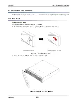
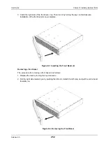
Chapter 8 Installing Optional Parts
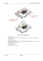
4. Insert new DIMMs.
Open the levers of the DIMM sockets, and then insert two new DIMMs into the sockets straight.
Fit the notch of the DIMM terminal to the wrong insertion prevention part of the socket.
Push the inserted DIMM all the way in, lock the DIMM and socket by putting the levers inside.
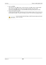
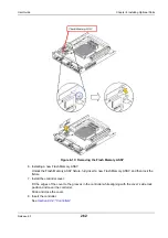
5. Remove the Flash Memory ASSY.
Unlock the Flash Memory ASSY fixture (blue-circled in the illustration below), and then remove only
the Flash Memory ASSY on the side of the battery connector from the socket by pulling it upward.
Do not remove the other Flash Memory ASSY. Doing so might cause the disk
array to not reboot.
Summary of Contents for M100
Page 25: ...Release 6 0 25 User Guide About Warning Labels Power Supply AC Power Supply ...
Page 27: ...Release 6 0 27 User Guide About Warning Labels Battery ...
Page 29: ...Release 6 0 29 User Guide About Warning Labels Power Cable AC Power Supply ...
Page 40: ...Release 6 0 40 User Guide Chapter 1 Overview 1 2 1 4 Controller CONT ...
Page 48: ...Release 6 0 48 User Guide Chapter 1 Overview 1 2 3 3 Controller CONT ...
Page 260: ...Release 6 0 260 User Guide Chapter 8 Installing Optional Parts Figure 8 12 Removing the DIMMs ...
Page 459: ...NEC Corporation 7 1 Shiba 5 chome Minato ku Tokyo 108 8001 Japan URL http www necstorage com ...