background image


© NEC Corporation 2019     26 


Pixel Card 

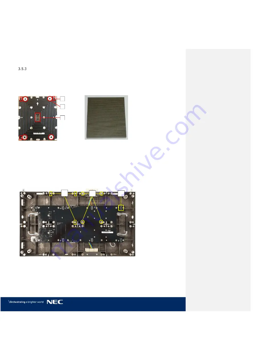
The Pixel cards display segments of the picture on the front. On the back, the Pixel card has 
three components, which keep the Pixel card in position on the cabinet: 


3 corner click-pins (A)   


4 magnets (B) 


1 Pixel card connector (C) 


Figure 21: Pixel Card – Back 


Figure 22: Pixel Card – Front 

Connections on the Hub board and the Cabinet 

For installation and operation, the Pixel card needs no cable connections to the Hub board or 
Cabinet. Three types of interfaces help to secure Pixel cards within the cabinet.   


Click-pin interfaces

 (D): counter-part to the corner click-pins on Pixel card; ensure the 

right position of the Pixel card on the cabinet. 


Level screws

 (E): counter-part to the magnets on the Pixel card; enable to adjust possible 

protrusion of the Pixel card to smoothen the surface of the LED Wall. 


Pixel card network interface

 (F): counter-part to Pixel card connector; for data 

transmission and power supply to the Pixel card. 


Figure 23: Pixel Card Interfaces on Hub Board and in Cabinet 

Summary of Contents for FE Series

Page 1: ...NEC FE Series LED Wall bundle Fine Pitch LED Video Display Indoor USER GUIDE For models LED FE012i2 LED FE015i2 LED FE019i2 LED FE025i2 LED FE031i2 LED FE038i2 2020 02 07 ...

Page 2: ...12i2 110 and LED FE019i2 110 4 4 Modules 17 Frameset for LED FE015i2 137 5 5 Modules 18 Frameset for LED FE019i2 165 6 6 Modules 18 3 4 Specification 19 3 5 LED Wall Components 20 Module 20 Cabinet 21 3 5 2 1 Corner Alignment Pins 22 3 5 2 2 Screw Connection for Cabinets 22 3 5 2 3 Grip Handles 23 3 5 2 4 Cabinet Hanger Pins 24 3 5 2 5 Power Supply Socket 25 Pixel Card 26 Hub Board 28 Power Supply...

Page 3: ...inets 45 6 4 Connect Power and Data Cables 46 Connect Data Cables 46 Connect Power Cables to the Power Bar 46 Check the Power Supply and Data Connection of the Modules 47 6 5 Install Frame Covers 47 6 6 Install Pixel Cards 50 7 GETTING STARTED 52 7 1 Info on the Connection Setup 52 7 2 Install Controller Software NovaLCT 52 7 3 Configure the Screen in NovaLCT Loading scr Files 53 7 4 Configure the...

Page 4: ...e European Union 81 12 2 Outside the European Union 81 13 COPYRIGHT AND DISCLAIMER 82 13 1 Copyright 82 13 2 Disclaimer 82 14 APPENDIX 83 14 1 Cable Plans 83 LED FE012i2 110 LED FE019i2 110 Data Connections 83 LED FE012i2 110 LED FE019i2 110 Power Connections 83 LED FE015i2 137 Data Connections 84 LED FE015i2 137 Power Connections 84 LED FE019i2 165 Data Connections 85 LED FE019i2 165 Power Connec...

Page 5: ...ing 29 Figure 28 Pin Connection from PDU to PSU 29 Figure 29 Signal Lights on the Back of the Module 30 Figure 30 Signal Light Interface Connected to Hub Board 30 Figure 31 Power Bar with Cable Exit Point 30 Figure 32 Ventilation Space for Buried Installation 31 Figure 33 Ventilation Space for On Wall Installation 32 Figure 34 Cabinet Alignment Bracket 33 Figure 35 Cabinet Boxes inside Case 35 Fig...

Page 6: ...ting the Import of the fcg Files 58 Figure 84 Successfully Import of the fcg Files 58 Figure 85 Start Screen Starting Calibration 59 Figure 86 Start Screen for Screen Calibration 59 Figure 87 Screen Calibration Register Manage Coefficients 60 Figure 88 Starting Screen Module Flash 60 Figure 89 Flash Module after loading Module Calibration Data 61 Figure 90 Flash Module after saving Module Calibrat...

Page 7: ... NEC Corporation 2019 7 Figure 120 Behind Hub Board Power Supply and PDU with PDU Shielding 77 Figure 121 Removing Shielding PDU 78 ...

Page 8: ...l 4 4 5 5 6 6 37 Table 7 Frame Support Installation requirements 38 Table 8 Number and Position for Anchor Points 40 Table 9 Power Bar Installation Requirements 41 Table 10 Cabinet Installation Requirements 42 Table 11 Cable Connection Requirements 46 Table 12 Frame Cover Installation Requirements 47 Table 13 Pixel Card Installation Requirements 50 Table 14 Main Menus and Functions 63 Table 15 Mon...

Page 9: ...dicate the severity of a potential hazard WARNING A warning for a potentially hazardous situation that can result in death personal injury or property damage if not adhered to Caution A recommendation for a potentially hazardous situation that may result in personal injury or property damage if not adhered to Notice A recommendation for a potentially hazardous situation that may result in property...

Page 10: ...NS and or respectively authorized personal may carry out repairs service and maintenance work on the system A case of service occurs as soon as one component is damaged in any way is not fully functional any more Only trained personnel such as electricians or NEC personnel may connect the internal power supply to mains power supply 2 2 Personal Protection WARNING Electric shock hazards Follow the ...

Page 11: ...es Check cables regularly Replace damaged cables immediately they are not user serviceable Caution Risk of fire and product damage by aggressive substances Keep the system away from aggressive substances inflammable gases and vapors Caution Risk of fire injuries and product damage Keep the system away from flammable material Never block the air ventilation spaces around the LED Wall Keep them free...

Page 12: ...the air ventilation holes Keep them free at all times To protect the power cable against overload maximum 10 cabinets shall be wired in a row at 100 V AC or 20 modules at 240 V AC The total load must not exceed 16 A per cable To avoid risk of fire due to overheating of the cables only use the supplied cables that are meant for the system and its components Damaged cables must be replaced by new ca...

Page 13: ...ed transition ramps cable channels Protect the cable against kinks and sharp edges Notice Use a TN S power distribution system with a separate neutral and grounding conductor Due to voltage differences in the neutral conductor large ground current loops can be avoided therewith The complete electrical system should be protected by an appropriately rated disconnect switch circuit breakers over volt...

Page 14: ...struction manual may cause harmful interference to radio communications Operation of this equipment in a residential area is likely to cause harmful interference in which case the user will be required to correct the interference at his own expense Supplier s Declaration of Conformity for USA only This device complies with Part 15 of FCC Rules Operation is subject to the following two conditions 1...

Page 15: ...TRL660 PRO Spare Parts Set White ESD gloves Internal power cables Internal data cables External data cable LED Wall to video controller 20 m STP Cat5e USB flash drive with NovaLCT software calibration data RCFGX File for Receiving cards 3 2 List of Parts Table 1 Materials and Parts Delivered for Each Bundle Pos Item Specification Qty 4 4 Qty 5 5 Qty 6 6 Photo 1 Pixel card 152 171 10 mm 128 200 288...

Page 16: ...nk 2 2 2 14 Frame cover top 1 1 1 15 Screw for frame cover side M8 16 Hexagon socket head screw 6 8 8 16 Screw for frame cover top M8 16 Hexagon socket head screw 4 4 4 17 Screw for cabinet to Power bar M8 16 Hexagon socket head screw 8 10 12 Cabinet alignment bracket 10 12 14 Screw for connecting cabinets Hexagon socket head screw 64 100 144 Ethernet cable between Hub boards 12 20 30 Commented A1...

Page 17: ...ED FE012i2 110 LED FE019i2 110 LED FE015i2 137 LED FE019i2 165 Display size inch cm 110 279 137 348 165 419 Dimensions incl frame W H 2472 1488 mm 3080 1830 mm 3688 2172 mm Weight 259 kg 381 kg 503 kg See section 3 2 List of Parts for complete list of parts names and quantities The positions given in the following illustration refer to the List of Parts Frameset for LED FE012i2 110 and LED FE019i2...

Page 18: ...EC Corporation 2019 18 Frameset for LED FE015i2 137 5 5 Modules Figure 2 Frameset for LED FE015i2 137 5 5 Modules Frameset for LED FE019i2 165 6 6 Modules Figure 3 Frameset for LED FE019i2 165 6 6 Modules ...

Page 19: ...er max average 800 W m 125 W module 280 W m 57 W module Power tolerance 10 Viewing angle HOR L R 85 85 VER U L 85 85 Brightness 700 cd m Brightness tolerance 10 Pixel density per m 623 269 398 892 277 008 Certifications CE FCC Class A RoHS Contrast ratio 5 000 1 Operating temperature 20 C to 40 C Operating humidity 10 to 80 relative humidity non condensing LED Lifetime 50 brightness 100 000 hours ...

Page 20: ...ture 3 3 Framesets for Bundles Power bar 3 5 7 Power Bar Figure 4 LED Wall Components Module The module consists of eight Pixel cards and a cabinet For information on Type A and B modules cabinets see 3 5 2 Cabinet Figure 5 Type A Module Front View Figure 6 Module Back Side Figure 7 Type B Module Open Figure 8 Type A Module Open ...

Page 21: ...ice through the cabinet system Figure 9 Type A Cabinet Front Type A Cabinets have two connectors for power Power supply socket one on the top and one at bottom of the case see Figure 10 Type B Cabinets have only one connector for power Power supply socket on the bottom of the case This allows for the frame cover top to be placed directly on top of the housing for perfect closure of the frame Figur...

Page 22: ...t Pins 3 5 2 2 Screw Connection for Cabinets The Screw connections between the cabinets guarantee quick installation and easy maintenance Each cabinet has two sets of Screw connections two sets of Allen screw anchors left and top Error Reference source not found B two sets of Counter plates right and bottom C This design allows modules to interconnect tightly in order to create a seamless LED Wall...

Page 23: ...le center left and right from the hub board These provide for easy handling during installation and maintenance in the open position and conveniently collapse into the cabinet when not in use Figure 13 Figure 14 Figure 13 Grip Handle in Open and Closed Positions Figure 14 Grip Handles in Use Open Closed D ...

Page 24: ...the cabinet Figure 16 and secured on the inside of the cabinet Figure 17 H If used as fixed installation optional matched connectors can be adopted to connect the Corner alignment pin and support frame Figure 15 Cabinet Hanger Pin Figure 16 Installing Cabinet Hanger Pins Figure 17 Cabinet Hanger Pin Connectors H ...

Page 25: ...he sockets interconnect two cabinets of a column Figure 19 The socket is connected to the Power distribution unit PDU wiring C The sockets wire to the PDU Figure 20 D and ground E on the cabinet The PDU in turn connects to the Power supply unit F via the hub board s power supply connector see also Figure 26 D p 28 Figure 18 Power Supply Sockets Top and Bottom Figure 19 Connected Sockets Figure 20 ...

Page 26: ... no cable connections to the Hub board or Cabinet Three types of interfaces help to secure Pixel cards within the cabinet Click pin interfaces D counter part to the corner click pins on Pixel card ensure the right position of the Pixel card on the cabinet Level screws E counter part to the magnets on the Pixel card enable to adjust possible protrusion of the Pixel card to smoothen the surface of t...

Page 27: ...tect the electronic surface between the LEDs of the Pixel card PCB In combination with our high end LED chips A the mask B is necessary to get the best black values which result in a high contrast ratio of the screen Figure 24 LED Chip and Usage of the Black Masks A B ...

Page 28: ...thernet port has no function 16 screw connections to cabinet C To secure the Hub board in the cabinet Figure 25 Hub Board Front The backside of the Hub board has several interfaces for data and power distribution Figure 26 4 pin connectors to Power supply unit D Distribute the power from PSU to the Hub board e g for the Pixel cards or Receiving card 1 Power good connector E Sends status of power s...

Page 29: ...PDU shielding B2 The PDU shielding protects the high voltage components from being touched by accident Do not remove while power is connected 1 Power supply interface to Hub board C Counter part to the Hub board s four pin connector to supply the Hub board with power Figure 27 Behind Hub Board Power Supply with Wired PDU with PDU Shielding The PDU connects to the PSU via three pin connectors D for...

Page 30: ...h the Signal light cable B Figure 30 Signal Light Interface Connected to Hub Board Power Bar The Power bar is the LED Wall component for the distribution of data and power It is located at the bottom of the LED Wall and connects to each row of modules via the Network and power supply socket The Power bar also serves as cable conduit The cables for power supply and data transmission run inside the ...

Page 31: ...ventilation space Notice For installation conditions deviating from the information given below more calculations regarding the air flow and cooling of the system are necessary If you have questions please contact NEC DISPLAY SOLUTIONS see 1 2 Service Support in Europe Minimum Ventilation Spaces for Buried Installation in Wall Alcove Figure 32 Ventilation Space for Buried Installation A B C D E mi...

Page 32: ...pends on each particular project Depending on the structural design and environmental temperature it may be necessary to add an external cooling To integrate the ideal energy efficient air conditioner for the LED display you have to determine the capacity or size you need This is important for two reasons An undersized unit will not cool adequately the LED display in extremely hot weather An overs...

Page 33: ...umn For more information see 14 1 Cable Plans External Video controller to PC Signal cables to connect the video controller and a PC are included Refer to Table 4 to choose the correct signal cable for that task Table 4 Compatible Signal Cable Video Distributor DVI single link HDMI 3G SDI Cable included in delivery Cable included in delivery Cable not included in delivery 4 2 Cabinet Alignment Bra...

Page 34: ...H in mm Weight in kg Content Qty 4 4 Qty 5 5 Qty 6 6 A 1580 835 670 174 Cabinets Accessories Spare parts 2 3 4 B 1450 570 610 120 Pixel cards Accessories Spare parts 2 3 4 C 2500 400 315 70 Mounting parts Cover frames for 4 4 1 D 3100 375 315 100 Mounting parts Cover frames for 5 5 1 E 3720 400 315 135 Mounting parts Cover frames for 6 6 1 Total 5 cases 7 cases 9 cases ...

Page 35: ...net 3 Foam container 4 Cardboard box 5 Figure 36 Package Order of Module Box Pixel Cards Packaging Each wooden case B contains 8 carton boxes with each 8 Pixel cards individually packed Figure 37 Pixel Card Boxes inside Case One Pixel card box contains the following Foam cover 6 Antistatic bag 7 Pixel card 8 Foam container 9 Cardboard box 10 Figure 38 Package Order of Pixel Card Box 1 2 3 4 5 6 7 ...

Page 36: ... parts see chapter 10 Unpack the Components Open the wooden boxes carefully with a suitable tool Bend the hook upwards so the lid can be taken off Figure 41 Start with the case that contains the Wall frame set Take out the component boxes carefully and open them Continue with the cabinet box Take out the component boxes carefully and open them Figure 41 Hook on Wooden Box Continue with the Pixel c...

Page 37: ...table wall mounting equipment Before starting the installation Ensure that the installation site is suitable for the cable routing plan If necessary mark important points of the plan on the wall used for the installation Regarding the installation site Analyze the wall used for the installation and the weight of the complete LED Wall see Table 6 Choose installation equipment e g tools screws and d...

Page 38: ...pment e g drilling machine and fitting attachment head depending on mounting surface wall material condition Mounting material screws dowels etc depending on overall weight of chosen screen system mounting surface wall material condition Measurement tools e g rule spirit level Alignment bar Included in delivery flat black bar Equipment See for 3 3 Framesets for Bundles specifications related to Fr...

Page 39: ... anchor points to drill out See markings in figures below or the dimensions in Table 8 Use the spirit level to check the vertical alignment of the marks before drilling Figure 42 Positions for Anchor Points 4 4 Frameset Figure 43 Positions for Anchor Points 5 5 Frameset Figure 44 Positions for Anchor Points 6 6 Frameset ...

Page 40: ...ed drilling equipment to drill on marked positions If necessary use screw anchors raw plugs Remove any debris and wipe away drill shaving and dust particles Attach the Frame Supports Attach each vertical frame support onto the grid on the wall Check the distance of the frame elements using the Alignment bar Use the spirit level together with the Alignment bar to check the evenness Figure 45 and Fi...

Page 41: ...rewdriver Equipment Power bar Check the Evenness Use the Alignment bar and spirit level in combination to check the evenness between the vertical frame supports If necessary adjust top and bottom supports accordingly Bring Power Bar into Position Bring the Power bar into position to align interface to anchoring point Align the locating pin of the Power bar to the frame support interface Figure 47 ...

Page 42: ...binet Installation Requirements No of People 2 Prerequisites Frameset securely installed Power bar securely installed Tools Screwdriver Allen key Equipment Cabinets Cabinet hanger pins Cabinet alignment bracket Figure 49 Wall Mounting Installation Order of Cabinets 4 4 Frameset Install Cabinet Hanger Pins on the Backside On the workbench place cabinet front side down on a protected surface Install...

Page 43: ...Power supply socket Otherwise the connector may be pushed out and not function properly Figure 51 Installing the First Cabinet Install further cabinets until the first row is complete Figure 52 Installing Additional Cabinets First Row Connect each cabinet to its adjacent cabinets with the Screw connections Place a delivered Allen screw E in the screw connection anchor Only finger tighten the screw...

Page 44: ...top corner of the cabinet Figure 55 Vertical Alignment of Cabinets Secure Cabinet to Power Bar Connect the cabinets of the first row to the Power bar For this screw a M8 16 screw in the opening for the Screw connection at the bottom of the cabinets Screw the cabinets of the first row onto the Power bar with M8 16 screws Figure 56 Fastening of First Row to Power Bar I H ...

Page 45: ...rew E in the screw connection anchor Only finger tighten the screw to the Counter plate F in the other cabinet Figure 57 Locking Two Modules Notice Do not tighten the Screw connection too much Otherwise the cabinets cannot be aligned later on For the top row use type B cabinets only Proceed as described above Align Cabinets After all rows of cabinets are installed the cabinets have to be aligned w...

Page 46: ...wer Bar Prepare the power connection according to the cabling plans see 14 1 Cable Plans Each column of cabinets is wired to one terminal in the Power bar Connect the conductors of the external power cables L N PE to the terminals in the Power bar See also Figure 59 Prepare the data connection according to the cabling plans see 14 1 Cable Plans Each column of cabinets needs one data input cable fr...

Page 47: ...l from mains power to continue safely with the installation 6 5 Install Frame Covers The frame covers protect the LED Wall from any dust or other particles that could come in through the holes on the sides and the top Inside the frame covers are slot nuts The frame covers are attached to the LED Wall via screws which go through the Screw connection anchors into the slot nuts Info It is easier to i...

Page 48: ...ble the frame on the ground in front of the LED Wall Attach the frame cover links to the top frame cover with the pre installed screw D Attach the frame cover sides to the frame cover top and links with the pre installed screw D Figure 62 Frame Cover Links With two people carefully lift the frame cover and place it onto the LED Wall Figure 63 Installing Top Frame Cover Align the slot nuts in the f...

Page 49: ...astening the Side Frame Covers Slide the hooks on Power bar cover plate into the vertical key holes E on the Power bar Push the Power bar cover plate firmly to the right so it stays in place Figure 66 Installing Power Bar Cover Plate C E ...

Page 50: ...spiration salts flaking skin and or other forms of human excretory secretions The LED modules and their electrical components are sensitive to biological agents and exposure to such risks degradation of materials and performance Eliminate any static electricity from your body before touching the Pixel cards by touching an aluminum sash a door knob or some other metal object Pixel cards use a combi...

Page 51: ...he Pixel Cards Ensure that the surface of the LED Wall is even If a Pixel card sticks out minimize the protrusion with the level screws A in the cabinet Remove the Pixel card with the Service tool Figure 107 p 74 Adjust the level screws in the cabinet Re install the Pixel card and check if it is level to the other Pixel cards Figure 71 Level Screws The LED Wall is completely installed A ...

Page 52: ...creen Notice The NovaStar Controller is no product of NEC DISPLAY SOLUTIONS For detailed information on the NovaStar Controller see the respective manual for NovaStar Controller MCTRL660 PRO Download the current version at https www novastar tech download download controller 7 2 Install Controller Software NovaLCT To configure and check the functions of the controller you need to install the softw...

Page 53: ...n Settings Start the software NovaLCT Click the User U register and select Advanced Synchronous System User Login A see Figure 72 Figure 72 Advanced User Login Enter the password into the Password field The default password is admin Click the Login button to confirm the entry see Figure 73 The start screen refreshes automatically Result If the login is successful the interface below will appear se...

Page 54: ...menu button Result Screen Configuration opens The pop up opens see Figure 75 Figure 75 Pop Up Configurating the Screen Connection Click the Next button The screen refreshes see Figure 76 Figure 76 Start Screen Configuration Register Sending Card Default View ...

Page 55: ...e from the delivered USB flash drive and click Open button confirm the loading message with OK button Result The scr file will be loaded Click the Send to HW button to save the configuration Confirm the upcoming pop up message with OK Result The scr file will be saved After restart the configuration is available Figure 78 Save Configuration Notice If you do not save the configuration the system wi...

Page 56: ...and Figure 80 Close the software by clicking X button or the Close button Settings for bundles 4 4 5 5 and 6 6 Figure 79 Screen Settings for 4 4 Controller Figure 80 Screen Settings for 5 5 Controller left and 6 6 Controller right Commented A4 Doctima NEC Bitte prüfen ob weiterer Screenshot notwendig ist ...

Page 57: ... the Settings menu Choose Advanced Color Configuration see Figure 81 A new window will open see Figure 82 Figure 81 Starting Configuration Color and Brightness Settings Figure 82 Start Screen Configuration Color and Brightness Settings Click the Import button Select the fcg file from the delivered USB flash drive and open the file ...

Page 58: ...s line Figure 83 Starting the Import of the fcg Files Click the Send to HW button The settings are saved see Figure 84 Result The message that the data has been successfully saved appears in the status line The color and brightness settings are finished Figure 84 Successfully Import of the fcg Files Close the Advanced Color Configuration by clicking X button ...

Page 59: ... Installing All Pixel Cards Login as Advanced User Click the Calibration button The screen refreshes automatically see Figure 85 and Figure 86 Figure 85 Start Screen Starting Calibration Figure 86 Start Screen for Screen Calibration Select the Screen1 radio button ...

Page 60: ...Click on the Manage Coefficients tab see Figure 87 Figure 87 Screen Calibration Register Manage Coefficients Click on Module Flash Result The module flash options will appear see Figure 88 Figure 88 Starting Screen Module Flash ...

Page 61: ...d The pop up message that the data has been successfully stored to the Receiving cards will appear see Figure 90 Result The screen with the exchanged Pixel cards should look calibrated now Figure 90 Flash Module after saving Module Calibration Data Click on Save to HW button and go back to main window by clicking X button Repeat all steps for Screen 2 Click on the Return button to be able to selec...

Page 62: ...is disabled If calibration setting Disable Calibration is chosen switch to Chroma Calibration to enable calibration and click on the Save button see Figure 92 Result While switching you will already see calibration effect Figure 92 Calibration is enabled Close Screen Calibration windows by clicking on the X Result The Screen Calibration has been finished for both screens ...

Page 63: ...d User Configure the LED screens Brightness Adjust the brightness of the LED display There are two ways for brightness adjustment automatic brightness and manual brightness Multi function Card Open the page for Multi function card configuration Multiple screen Management Open the page for combined display configuration The management of brightness control and monitoring of multiple LED displays is...

Page 64: ...rdinates Tools Calibration Calibrate the screen and manage the calibration coefficients Screen Control Perform the screen control functions which include Black Out Freeze and Normal Besides self test options are also provided Monitoring View the monitoring results or set the monitoring parameters Led Error Detection Detect LED errors after the screen has been properly configured Multi batch Adjust...

Page 65: ...ys testing Calculator Open the Microsoft Windows calculator External Program Add an external program DHCP Service Obtain the IP address assigned by the server User Advanced User Login Log in the synchronous system with the password admin Enter Demonstration mode Experience the related functions of the synchronous system No hardware connection is required Use the password admin Connect Asynchronous...

Page 66: ...ct Advanced Synchronous System User Login A see Figure 94 Figure 94 Advanced User Login Enter the password into the Password field The default password is admin Click the Login button to confirm the entry see Figure 95 If the Login is successful the interface below will appear see Figure 96 The start screen refreshes automatically Figure 95 Entering Password Figure 96 Interface after successful Lo...

Page 67: ... Sending cards Receiving Card Check the wiring of the Receiving card and the Power supplies Temperature Check the temperature of each module and the Operating status of each individual Power supply solution Monitoring Refresh Update the monitored data Modify refresh period and re read times when reading the status failed at the refresh period interface where in the period is the period of refreshi...

Page 68: ...toring view of the Receiving card and the Power supplies offers checking the wiring Errors will be shown in colored surfaces The color codes are defined in the interface itself Click the Monitoring button to open the monitoring interface see Figure 99 Result The Monitoring interface will open By default the Monitoring view for the Receiving cards is opened see Figure 100 Figure 99 Starting the Mon...

Page 69: ... NEC Corporation 2019 69 Figure 100 Start Screen Monitoring Receiving Cards and Power Supplies ...

Page 70: ...e itself Click the Monitoring button to open the Monitoring interface see Figure 101 Result The Monitoring interface will open By default the Monitoring view for the Receiving cards is opened see Figure 102 Figure 101 Starting the Monitoring Function Figure 102 Start Screen Monitoring Receiving Cards and Power Supplies Click Sending Card button to switch to the Monitoring view for the Sending card...

Page 71: ... status of each individual power supply solution Errors will be shown in colored surfaces The color codes are defined in the interface itself Click the Monitoring button to open the monitoring interface see Figure 104 Result The Monitoring interface will open By default the Monitoring view for the Receiving cards is opened see Figure 105 Figure 104 Starting the Monitoring Function ...

Page 72: ...019 72 Figure 105 Start Screen Monitoring Receiving Cards and Power Supplies Click the Temperature button to switch to the Monitoring view for the temperature see Figure 106 Figure 106 Start Screen Monitoring Temperature ...

Page 73: ... the LED Pixel cards with a damp cloth Notice Clean the components of the LED Wall very carefully to avoid damaging the surfaces Do not alter the cleaning procedure otherwise pixels or Pixel cards can be permanently damaged Under normal conditions the recommended cleaning interval of the LED display is every six months Before cleaning Disconnect the LED Wall from mains power Lock electric power su...

Page 74: ...Charger Use the Service tool to remove the Pixel cards in a safe and easy way The Service tool comes with a battery and charger for wireless usage Ensure the Service tool is charged properly before using it Usage Set the air pressure regulator on the Service tool to Max Push the Service tool on a Pixel card and hold the red button A The Service tool creates a vacuum that will suck out the Pixel ca...

Page 75: ...erial and anti static plastic bag for the Pixel cards Heat conducting paste for servicing the power supply Change the Pixel Cards The Front service takes only 10 seconds to exchange a pixel module This convenience is due to the unique magnet interfaces A corner click pins B and Pixel card connector C Figure 109 Pixel Card Notice During the removal process put your free hand below the Pixel card re...

Page 76: ...thout Pixel Cards Remove the Hub Board For servicing the Hub board you need to remove the Pixel cards first see 9 5 1 Disconnect the Ethernet connections A from the Hub board Remove the 16 screws B which connect the Hub board to the cabinet Figure 112 Screws on Hub Board Pull the Hub board straight off the cabinet Be careful not to damage the Power supply interface C on the Hub board and the PSU D...

Page 77: ...heir connectors Replace the Receiving card To replace the Receiving card follow the instructions in reverse order Figure 114 Replacing the Receiving Card Change the Power Supply System For servicing the power supply you first need to remove the Pixel cards see 9 5 1 and the Hub board see 9 5 2 Now the power supply in the cabinet is accessible The following components contribute to the power supply...

Page 78: ...PDU To reinstall the replaced PDU follow the steps in reverse order Replace the Power Supply Unit To replace the PSU remove the Power distribution unit PDU first See above for instructions Remove the two screws G Take the PSU carefully off Place the PSU upside down so the heat conducting paste shows upwards and no other parts become dirty from it Before replacing the PSU distribute some heat condu...

Page 79: ...e Order no Cat Cable 80000129 Pixel Card 1 2 Pitch 1 5 Pitch 1 9 Pitch 80000193 80000162 80000194 Black Masks 1 5 Pitch 1 9 Pitch 80000130 80000144 Power Distribution Unit 80000127 Power Supply Unit 80000124 Receiving Card 80000123 Hub Board 80000170 ...

Page 80: ...nal input Check the green LED of the Receiving card is flickering regularly or not fast flickering means no signal 1 Check if the cable connector assembly is stable 2 Check whether the cable is short circuited 3 Check the power of the Receiving card In case the above three points do not fix the problem please exchange the Receiving card Module not working Use a multimeter to test the module The vo...

Page 81: ...cludes monitors and electrical accessories such as signal cables or power cords When you dispose of such products please follow the guidance of your local authority or ask the shop where you purchased the product or if applicable follow applicable legislation or agreement you may have The mark on electrical and electronic products my only apply to the current European Member States 12 2 Outside th...

Page 82: ...cifications measurements weights and properties are not guaranteed The manufacturer reserves the right to make product alterations within legal provisions as well as changes to improve product quality NEC DISPLAY SOLUTIONS shall not be liable for personal injury or damage to materials caused by failure to observe this warning and safety information of this manual Furthermore NEC DISPLAY SOLUTIONS ...

Page 83: ... NEC Corporation 2019 83 14 APPENDIX 14 1 Cable Plans LED FE012i2 110 LED FE019i2 110 Data Connections LED FE012i2 110 LED FE019i2 110 Power Connections ...

Page 84: ... NEC Corporation 2019 84 LED FE015i2 137 Data Connections LED FE015i2 137 Power Connections ...

Page 85: ... NEC Corporation 2019 85 LED FE019i2 165 Data Connections LED FE019i2 165 Power Connections ...

Reviews: