background image

- 4 - 


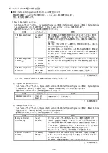
● SW RAID有効時、内蔵DVDドライブ(N8151-137/138)が2個表示される件について 

システム ROM v2.00 (02/02/2019)以上、v2.32 (03/09/2020)未満の場合、Embedded SATA Configuration 設定(*1)を
[Smart  Array  SW  RAID  Support]設定時、運用環境により Disk  Utilities メニュー(*2)に内蔵 DVD 
ドライブ情報が 2 個表示されます。 
どちらのドライブを選択した場合でも同じ内蔵 DVD ドライブの情報が参照できます。 

(*1) 「System Configuration > BIOS/Platform Configuration (RBSU) > Storage Options > SATA Controller 

Options > Embedded SATA Configuration」 

(*2) 「System Configuration > HPE Smart Array S100i SR Gen10 > Disk Utilities」 


● 工場出荷時の設定について 

以下の項目については、工場出荷時に以下のように設定しています。 


(1) System Configuration > BIOS/Platform Configuration (RBSU) > Workload Profileを「Custom」に設定。 
(2) System Configuration > BIOS/Platform Configuration (RBSU) > Power and Performance Options > Minimum 

Processor Idle Power Core C-Stateを「No C-states」に設定。 

(3) System Configuration > BIOS/Platform Configuration (RBSU) > Power and Performance Options > Minimum 

Processor Idle Power Package C-Stateを「No Package States」に設定。 


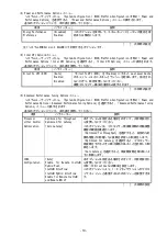
●iLOイベントログ(IEL)にIPMI Watchdog Timer Timeoutのログが登録される。 

システムROM  v2.62  (03/08/2022)が適用されている場合、かつIPMI  Watchdog  Timerオプションを「Disabled             
(出荷時の設定)」に設定している場合、iLOイベントログに下記のIPMI  Watchdog  Timer  Timeoutが登録される 
ことがあります。 
以下の手順を実施することで本問題が解消します。 

iLO IPMI Watchdog Timer Timeout: Action: None, TimerUse: 0x44, TimerActions: 0x00 
イベントクラス: 0x23 
イベントコード: 0xB3 


復旧手順: 
以下の復旧手順1、または2のどちらかを実施していただくことで、本問題が解消できます。 
 
復旧手順1 

(1) 装置の電源を切り、電源コードをコンセントから外す。 
(2) 30秒以上経過したのち、電源コードをコンセントに接続する。 

 
復旧手順2 
システムユーティリティより、IPMI Watchdog Timerオプションの設定を2回変更します。 

(1) POST中に<F9>キーを押下し、システムユーティリティを起動する。 
(2) System Configuration > BIOS/Platform Configuration(RBSU) > System Options > Server Availability > 

IPMI Watchdog Timerオプション を「Enabled」に設定する。 

(3) <F12>キーを押下し、設定を保存してシステムを再起動する。 
(4) POST中に<F9>キーを押下し、システムユーティリティを起動する。 
(5) System Configuration > BIOS/Platform Configuration(RBSU) > System Options > Server Availability > 

IPMI Watchdog Timerオプションを「Disabled」に設定する。 

(6) <F12>キーを押下し、設定を保存してシステム再起動する。 


Summary of Contents for Express5800/T120h

Page 1: ...Web S8 10 007 02 https www support nec co jp NEC S8 10 007 VMware ESXi VMware ESXi Web Web 1 Agentless Management Service iLO Channel Interface Driver https www support nec co jp NEC Agentless Managem...

Page 2: ...2 2 ROM Submit Fail For Form Question Submit Fail For Form Question OK Serial Number Product ID RSOD Red Screen of Death OS RSOD OFF ON RSOD OFF ON...

Page 3: ...nfiguration Lock SCL 1 SCL 2 SCL SCL SCL OS SCL SCL 3 SCL SCL 4 RBSU Halt on Server Configuration Lock failure detection SCL OS SCL RBSU DIMM PCI RESTful RBSU iLO 5 2 40 RESTful RBSU RBSU Backup and R...

Page 4: ...inimum Processor Idle Power Core C State No C states 3 System Configuration BIOS Platform Configuration RBSU Power and Performance Options Minimum Processor Idle Power Package C State No Package State...

Page 5: ...02 2019 1MB 1048576 3 ROM v1 36 02 14 2018 v1 36 02 15 2018 PCIe Slot X MCTP Broadcast Support X PCIe Slot ROM v2 10 05 21 2019 PCIe MCTP Options 1 2 PCIe Slot ROM 3 PCIe Slot 2 MCTP Broadcast v2 22...

Page 6: ...urity Access Settings Update Service Downgrade Policy Permanently disallow downgrades Permanently disallow downgrades iLO Permanently disallow downgrades iLO Set to factory defaults iLO Permanently di...

Page 7: ...OST Power On Self Test iLO iLO Web Information Overview UUID UUID iLO Web iLO 5 1 40 iLO Web iLO Web Virtual NIC Security iLO Virtual NIC iLO 5 BMC 1 iLO 5 2 10 2 18 Enabled NIC Windows Server 2012 R2...

Page 8: ...al Network Adapters OS OS iLO Web Device Inventory SAS N8116 83 iLO 5 2 31 iLO Web System Information Device Inventory SAS SAS Firmware Version N A Status Disabled iLO Web iLO 5 1 43 2 10 Information...

Page 9: ...O Web System Information Summary Subsystem and Devices Agentless Management Service AMS iLO 10 Agentless Management Service AMS OS Agentless Management Service AMS Agentless Management Service AMS iLO...

Page 10: ...r Pack Starter Pack Version S8 10 006 03 AMS 1 40 0 0 Starter Pack Version S8 10 006 03 AMS Starter Pack Web Agentless Management Service AMS 1 40 0 0 1 AMS net stop ams 2 C Program Files OEM AMS Serv...

Page 11: ...GBASE T 2ch N8104 183 10GBASE T 2ch N8104 185 10GBASE SFP 2ch N8104 187 25GBASE SFP28 2ch PCI to PCI PCI 1 LAN 2 LAN 3 IP DNS DNS 4 IP IP DNS DNS 5 CPU 6 3 IP DNS DNS 7 LAN 8 1 LAN IP IP set devmgr_sh...

Page 12: ...24 2 ESMPRO ServerManager Ver 6 Windows 2 ESMPRO ServerManager ESMPRO ServerManager Ver 7 Windows 1 Web ESMPRO Platform Management Kit https www support nec co jp View aspx id 9010109532 ESMPRO Server...

Page 13: ...O ServerManager Windows 1 ESMPRO ServerManager 2 ESMPRO ServerManager 3 ESMPRO ServerManager iLO MG Windows 3 1 5 3 2 4 iLO SNMP Trap VMware ESXi ESXi VMware vSphere 1 Heartbeat Lost Device I O Module...

Page 14: ...96 201 237 238 240 RAID N8103 239 OS SSD RAID SNMP Trap Web NEC https www support nec co jp View aspx id 3140108419 VMware ESXi 6 0 VMware ESXi 6 0 VMware ESXi 6 0 LAN OS LAN Disabled System Utilities...

Page 15: ...guration Utility BMC Configuration Utility 1 2 Memory Initialization Start POST Serial Number Product ID 1 BMC Configuration Utility iLO Warning 2 OK 3 Warning Warning 1 4 1 iLO 1 iLO 5 OK 6 ESC 7 Reb...

Page 16: ...uration BIOS Platform Configuration RBSU System Options Serial Port Options BIOS Serial Console and EMS BIOS Serial Console Port Disabled 2 System Configuration BMC Configuration Utility Setting Optio...

Page 17: ...d Thermal Options Thermal Configuration Optimal Cooling Increased Cooling 2 N8103 184 SAS iLO Web System Information Storage Storage Controller Status Unknown N8102 713 128GB RDIMM N8102 708 709 710 7...

Page 18: ...20 Minutes 30 Minutes IPMI Watchdog Timer Action 1 Power Cycle Power Down Warm Boot 1 ROM Version 2 54 2 Diagnostics Options System Configuration BIOS Platform Configuration RBSU System Options Diagn...

Page 19: ...bled Disabled Direct To UPI D2K Enabled Last Level Cache 5 Advanced Performance Tuning Options System Configuration BIOS Platform Configuration RBSU Power and Performance Options Advanced Performance...

Page 20: ...er Security Server Security UEFI Variable Access Firmware Control 1 Disabled Enabled UEFI BIOS Disabled UEFI Enabled BIOS UEFI UEFI 1 ROM Version 2 54 8 PCIe Devices Configuration System Configuration...

Page 21: ...ystem Configuration BIOS Platform Configuration RBSU PCIe Devices Configuration Advanced PCIe Configuration PCIe MCTP Options PCIe MCTP Options PCIe Slot XX MCTP Broadcast Support Enabled Disabled PCI...

Page 22: ...tion BIOS Platform Configuration RBSU Advanced Options Advanced Debug Options Advanced Debug Options Advanced Crash Dump Mode Disabled Enabled Enabled AHS 10 Embedded Applications Embedded Application...

Page 23: ...1 11 1 DIMM 1 5TB 5 3 0TB 5 P 86 1 System Configuration BIOS Platform Configuration RBSU System Options Memory Operations Advanced Memory Protection Mirrored Memory with Advanced ECC Support System C...

Page 24: ...00 7 SATA 5 DVD N8154 122 SATA P 147 1 23 1 RAID RAID N8103 189 195 RAID 5 RAID 6 RAID 50 RAID 60 RAID RAID RAID N8103 189 195 N8103 190 191 196 201 RAID 0 1 1 RAID 1 2 2 RAID 5 3 RAID 6 3 RAID 10 4...

Page 25: ...0Hz 3Hz AC N8181 159 500W 80 PLUS Platinum 2 AC100 240V 10 50 60Hz 3Hz AC N8181 160 800W 80 PLUS Platinum 2 AC100 240V 10 50 60Hz 3Hz Express5800 T120h Windows Windows P 17 3 1 2 2 1 1 2 1 P 68 4 1 2...

Page 26: ...nec iscsitarget iscsidisk target P97 e Advanced Power Options Redundant Power Supply Mode Balanced Mode UPS HighEfficiency Mode UPS High Efficiency Mode UPS Auto UPS Balanced Mode 2 High Efficiency Mo...

Page 27: ...4 5 6 7 8 9 10 11 12 DIMM 1 1 DIMM 2 1 2 DIMM 3 1 2 3 DIMM 4 4 3 1 2 DIMM 5 5 4 1 2 3 DIMM 6 6 5 4 1 2 3 DIMM 7 6 5 4 7 1 2 3 DIMM 8 4 8 3 7 5 1 6 2 DIMM 9 6 5 4 7 1 8 2 9 3 DIMM 10 6 5 10 4 9 7 1 8...

Page 28: ...11 3 DIMM16 8 16 6 14 10 2 12 4 7 15 5 13 9 1 11 3 DIMM17 8 16 6 14 10 2 12 4 11 9 7 13 1 15 3 17 5 DIMM18 12 10 8 14 2 16 4 18 6 11 9 7 13 1 15 3 17 5 DIMM19 12 10 8 14 2 16 4 18 6 11 9 19 7 17 13 1...

Page 29: ...are Tower Select your server model Please check latest information and versions on ESMPRO portal site before using NEC ESMPRO Manager NEC ESMPRO ServerAgentService and Express Report Service Express R...

Page 30: ...controllable However theserver may recover from the RSOD by turning off and then on the power again To recover from this condition power off and then on the server again If the problem persists contac...

Page 31: ...CI option card Notice of the backup and restore of RBSU Settings by REST ful interface tool In the case of iLO5 firmware version 2 40 or later backup and restore of RBSU Settings should be done from B...

Page 32: ...System Utilities 3 In System Configuration select RBSU System Options Server Availability Then set the IPMI Watchdog Timer option to Enabled 4 Press the F12 key save the change and then restart the s...

Page 33: ...system ROM of the following versions when the settings are tried to be saved the pop up 3 appears and the settings are not saved As a result the pop ups 2 will be displayed as many as the number of th...

Page 34: ...setting Permanentlydisallowdowngrades isset downgradeofanyfirmwarecannotbedoneafterward Thesetting of this Permanently disallow downgrades is permanent and irreversible and users cannot change this se...

Page 35: ...screen display of UUID in iLO Web interface If the iLO is reset during POST execution the display of UUID and UUID logic in iLO Web interface Information Overview page may be corrupted When any corrup...

Page 36: ...aregreaterthan orequal to1 43 and lower than2 10 LastFirmware ScanResult is displayed in Information Security Dashboard Do not click this Hyperlink If you click this link by mistake you won t be able...

Page 37: ...m the status from iLO Web interface System Information Summary Subsystems and Devices Agentless Management Service If the status of Agentless Management Service AMS is Unknown or Not available iLO can...

Page 38: ...S8 10 006 03 you need to update theAMS separately For further explanation about the updating please check the Starter Pack website If you want to useAgentless Management Service AMS 1 40 0 0 please do...

Page 39: ...ddress automatically for IP address and Obtain DNS server address automatically for DNS address 5 Follow the user s guide to add a CPU board 6 Set IP address sub netmask default gateway preferred DNS...

Page 40: ...ESMPRO Manager For details refer to Chapter 2 Installation in NEC ESMPRO Manager Ver 6 Installation Guide Windows PDF Phenomena regarding iLO Receiving Information ilo_en mtb Intend for users of NEC...

Page 41: ...1 38 is applied In case that the screen display of Heartbeat Lost sensor Health vCenter Status shows Warning Yellow after ESXi completes boot for the ports whose cables are connected the Warning Yell...

Page 42: ...it of the number of LAN ports which VMware ESXi 6 0 defines will be exceeded Therefore please set the embedded LAN to Disabled in the BIOS settings before installing OS System Configuration BIOS Platf...

Page 43: ...es changing the settings of BMC Configuration Utility may display the following pop up before rebooting the iLO 2 Press OK to proceed 3 The iLO will start to reboot and then the following pop up appea...

Page 44: ...the default settings 11 The server restarts automatically and the POST screen appears 12 Press the F9 key to enter the System Utilities 13 SettheproperSerialNumberandProductID indicatedonthepull outta...

Page 45: ...ller N8103 184 please leave slots 2 and 4 blank with no PCI card installed Configure System Utilities as below System Configuration BIOS Platform Configuration RBSU Advanced Options Fan and Thermal Op...

Page 46: ...the table below Option Parameter Description Embedded Diagnostics Enabled Disabled This product does not support it Default setting 3 Memory Options Menu When you select System Configuration BIOS Plat...

Page 47: ...nd Remote WViLF Enable Disable IODC IO Direct Cache Generate snoops instead of memory lookups for remote InvItoM IIO and or WCiLF cores Default setting 7 Trusted Platform Module Options Menu When you...

Page 48: ...dvanced PCIe Configuration PCIe MCTP Options from the System Utilities the PCIe MCTP Options menu appears For details about the additional options see the table below Option Parameter Description PCIe...

Page 49: ...optionto enable theAdvancedCrash DumpMode When enabled the systemwillbeconfiguredtologadditionaldebuginformationtotheActiveHealth System logs when an unexpected system crash is experienced This optio...

Page 50: ...configuration No DIMM is factory installed in standard configuration P 73 1 11 1 Maximum supported memory size The maximum memory size supported on the server 5points 1 5TB 3 0TB P 79 1 Memory Mirrori...

Page 51: ...per MULTI N8151 138 7 Connect the optical disk drive connector to the onboard SATA port 5 connector on the motherboard with the SATA cable for optical disk drive K410 375 00 Wire the cables as shown b...

Page 52: ...iSCSI Configuration Menu 4 points iSCSI Boot Configuration iSCSI Configuration P 103 b TLS HTTPS Options Menu Advanced Secure Settings Advanced Security Settings P 104 Advanced Secure Settings Menu Ad...

Page 53: ...of installation may be different on x1CPU configuration x2CPU configuration and mounted number of the DIMM When only CPU1 is mounted DIMM slot number 1 2 3 4 5 6 7 8 9 10 11 12 DIMM Mounted number and...

Page 54: ...11 3 17 DIMM 8 16 6 14 10 2 12 4 11 9 7 13 1 15 3 17 5 18 DIMM 12 10 8 14 2 16 4 18 6 11 9 7 13 1 15 3 17 5 19 DIMM 12 10 8 14 2 16 4 18 6 11 9 19 7 17 13 1 15 3 5 20 DIMM 12 10 20 8 18 14 2 16 4 6 11...

Reviews: