background image

1. Installing Internal Optional Devices 


Express5800/GT110e  User’s Guide 

87 

Chapter 2  Preparations 

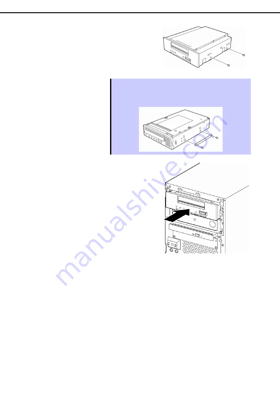
5.  Attach the two screws you removed in step 5 to the 

right side of the file device. 


Tips 

  If installing N8151-90/101/102/103, put the plate for device that was provided 

with the server on the right side of the device and install it to the front of the 
server by using the two dedicated screws. 

  The plate for device has circular holes to the front and long holes to the back. 


6.  Insert the file device. 


Summary of Contents for EXPRESS5800/GT110e

Page 1: ...s5800 Series 10 020 05 101 01 July 2012 First Edition NEC Corporation 2012 Express5800 GT110e EXP280A User s Guide Model Number N8100 1890F Chapter 1 General Description Chapter 2 Preparations Chapter 3 Setup Chapter 4 Appendix ...

Page 2: ...ons connection of peripheral devices and ideal location for this server Chapter 3 Setting Up Your Server System BIOS configurations and summary of EXPRESSBUILDER Chapter 4 Appendix Specifications and other information PDF Installation Guide Windows Chapter 1 Installing Windows Installation of Windows and drivers and important information for installation Chapter 2 Installing the Bundled Software I...

Page 3: ...12 Latest editions 12 Precautions for Use Be Sure to Read 13 Safety precautions 13 Symbols used in this document and on warning labels 14 Safety notes 15 General 15 Power supply and power cord use 16 Installation relocation storage and connection 18 Cleaning and working with internal devices 19 During operation 20 Warning labels 21 Handling precautions for proper operations 22 Chapter 1 General De...

Page 4: ...cautions 41 1 2 Anti static Measures 42 1 3 Overview of Installation and Removal 43 1 4 Removing the Side Cover 44 1 5 Removing the Front Bezel 45 1 6 Internal Flash Memory 46 1 6 1 Installation 46 1 6 2 Removal 46 1 7 DIMM 47 1 7 1 Maximum supported memory size 48 1 7 2 Installation order 48 1 7 3 Installation 49 1 7 4 Removal 50 1 8 Use of Internal Hard Disk Drives in the RAID System 51 1 8 1 No...

Page 5: ...llation 72 1 11 2 Removal 75 1 12 2 5 inch Hard Disk Drive 76 1 12 1 Replacing HDD cage 77 1 12 2 Installation 79 1 12 3 Removal 82 1 13 Optical Disk Drive 83 1 13 1 Replacing drives 83 1 13 2 Removal 84 1 14 File devices 85 1 14 1 Installation 85 1 14 2 Removal 88 1 15 Connecting cables 89 1 15 1 Interface cables 89 1 15 2 Power cables 94 1 16 Attaching the Front Bezel 96 1 17 Installing the Side...

Page 6: ...tility 109 2 3 Description on On Screen Items and Key Usage 110 2 4 Cases that Require Configuration 112 3 EXPRESSSCOPE ENGINE 3 114 3 1 Overview 114 3 2 EXPRESSSCOPE ENGINE 3 Network configuration 115 4 EXPRESSBUILDER 117 4 1 Features of EXPRESSBUILDER 117 4 2 Starting EXPRESSBUILDER 117 5 Installing Software Components 118 6 Turning Off the Server 119 Chapter 4 Appendix 120 1 Specifications 121 ...

Page 7: ...ccur Note Indicates items that must be confirmed when handling the server or operating software Tips Indicates information that is helpful to keep in mind when using this server Optical disk drives This server is equipped with one of the following drives depending on the order at the time of purchase These drives are referred to as optical disk drives in this document DVD ROM drive DVD Super MULTI...

Page 8: ...r 2003 R2 Standard Windows Server 2003 R2 Enterprise Windows Server 2003 2 Windows Server 2003 Standard Windows Server 2003 Enterprise Windows 7 Windows 7 Professional 64 bit x64 Edition Windows 7 Professional 32 bit x86 Edition Windows Vista Windows Vista Business 64 bit x64 Edition Windows Vista Business 32 bit x86 Edition Windows XP Windows XP Professional x64 Edition Windows XP Professional Wi...

Page 9: ...or trademarks of Adaptec Inc of the United States LSI and the LSI logo design are trademarks or registered trademarks of LSI Corporation Adobe the Adobe logo and Acrobat are trademarks of Adobe Systems Incorporated DLT and DLTtape are trademarks of Quantum Corporation of the United States PCI Express is a trademark of Peripheral Component Interconnect Special Interest Group Linux is a trademark or...

Page 10: ...on d Industrie Canada Cet appareil numérique de la classe A est conforme à la norme NMB 003 du Canada CE Australia and New Zealand Statement This is a Class A product In domestic environment this product may cause radio interference in which case the user may be required to take adequate measures EN55022 BSMI Statement Disposing of your used product In the European Union EU wide legislation as imp...

Page 11: ...二苯醚 PBDE 印刷线路板 HDD DVD等 机箱 支架 电源 键盘 其他 电缆 鼠标 等 表示该有毒有害物质在该部件所有均质材料中的含量均在SJ T11363 2006标准规定的限量要求以 下 表示该有毒有害物质至少在该部件的某一均质材料中的含量超出SJ T11363 2006标准规定的限量要 求 部件名称 有毒有害物质或元素 Vietnam RoHS information relevant for Vietnam market Complying with CIRCULAR No 30 2011 TT BCT Hanoi August 10 2011 Temporary regulations on content limit for certain hazardous substances in electrical products ...

Page 12: ...or omissions please contact your retailer 5 Regardless of these 4 items NEC Corporation assumes no responsibility for effects resulting from operations 6 The sample values used in this document are not the actual values Keep this document nearby so that you may refer to it as necessary Latest editions This document was created based on the information available at the time of its creation The scre...

Page 13: ...r serious personal injury CAUTION Indicates there is a risk of burns other personal injury or property damage Precautions and notices against hazards are presented with one of the following three symbols The individual symbols are defined as follows Attention This symbol indicates the presence of a hazard if the instruction is ignored An image in the symbol illustrates the hazard type Prohibited A...

Page 14: ...entified Prohibited Actions Do not disassemble repair or modify the server Otherwise an electric shock or fire may be caused Do not touch the server with wet hand Otherwise an electric shock may be caused Do not touch the component specified by this symbol Otherwise an electric shock or burn may be caused Do not use the server in the place where water or liquid may pour Otherwise an electric shock...

Page 15: ...esent If smoke odor or noise is present immediately turn off the server and disconnect the power plug from the outlet then contact the store where you purchased the product or your maintenance service company Using the server in such conditions may cause a fire Do not insert needles or metal objects Do not insert needles or metal objects into ventilation holes in the server or openings in the opti...

Page 16: ...If you want to use an AC cord set with a ground wire of class OI be sure to connect the ground wire before inserting the power plug into the outlet Before disconnecting the ground wire be sure to disconnect the power plug from the output Do not connect many cords into a single outlet by using extension cords The electric current exceeding the rated flow overheats the outlet which may cause a fire ...

Page 17: ... with staples or equivalents Do not pinch the power cord Keep chemicals away from the power cord Do not place any object on the power cord Do not alter modify or repair the power cord Do not use a damaged power cord replace the damaged power cord with a power cord of the same standard For information on replacing the power cord contact the store where you purchased the product or a maintenance ser...

Page 18: ...te corrosion such as NaCl or sulfur or conductive materials Failure to follow this warning may cause the wiring on the printed wiring board to short circuit leading to fire If you have any questions contact the store where you purchased the product or a maintenance service company Do not connect or disconnect any interface cable with the power cord of the server plugged to a power source Be sure t...

Page 19: ...en the server does not operate appropriately due to the dead battery contact the store you purchased the product or your maintenance service company Do not attempt to disassemble the server to replace or recharge the battery by yourself Disconnect the power plug before cleaning the server Be to power off the server and disconnect the power plug from a power outlet before cleaning or installing rem...

Page 20: ...r waste enters the server which may cause a fire or electric shock Do not place any object on top of servers Any weight on the server may cause the server to fall resulting in personal injury or property damage Do not leave the optical disk drive tray open Dust may get in the server when the tray is open which may result in a malfunction In addition bumping the open tray could cause personal injur...

Page 21: ...components This label is either attached or printed on the component to draw attention from users to potential hazards involved in handling the server Do not remove or black out this label and keep it clean If no label is attached or printed on the server or if there is a label coming off or stained contact the store where you purchased the product ...

Page 22: ... clean the server to prevent various types of failure Refer to Chapter 1 Maintenance 2 Daily Maintenance in Maintenance Guide for details about cleaning Momentary voltage drop may occur due to lightning strike To prevent this use of UPS is recommended For some optional devices that can be installed in the optical disk drive or 5 25 inch device bay it is possible to eject the tray or media by execu...

Page 23: ...e malfunctions and failures when these are used in such state To protect important stored data and property make sure to wait for a sufficient period to use the server and components in the operating environment Reference Time effective at avoiding condensation in winter 10 C or more differences between the room temperature and atmospheric temperature Disk devices Approximately 2 to 3 hours Tape m...

Page 24: ... from reflecting bright lights and to make the display contents easy to see Working without adjusting the display to a comfortable angle makes it difficult for you to maintain a proper posture and you will get tired easily Adjust the viewing angle before use Adjust the brightness and contrast of the display Display screens have functions to control brightness and contrast The most suitable brightn...

Page 25: ...es of this server and the name of each part 1 Introduction 2 Accessories Verify the condition of your server s accessories 3 Standard Features Check and maintain the server system by using the functions explained in this section 4 Names and Functions of Parts This section describes the name of each part contained in this server 1 1 ...

Page 26: ...on processor Intel Pentium processor Intel Celeron processor NEC s latest technology and architectures realize high power and high speed operation that cannot be matched by existing servers The server is designed with consideration of not only reliability but also expandability which enables you to use it as a network server Read this document before using the server thoroughly to fully understand...

Page 27: ...ure use Power cord Keyboard Mouse Screws for additional hard disk drives Screws for additional backup devices Getting Started EXPRESSBUILDER 1 SDR Update CD ROM 1 Documents are stored in EXPRESSBUILDER Adobe Reader is required to read the documents so make sure you have it installed in your PC Make sure you have all accessories and inspect them If an accessory is missing or damaged contact your sa...

Page 28: ... feature RAID System Disk Array also available as an option Auto rebuild function hot swapping supported BIOS password feature High availability Monitors OS stalls using the Watchdog timer Management utilities NEC ESMPRO ExpressUpdate Remote controlling featuer EXPRESSSCOPE Engine 3 RAID System management utility Universal RAID Utility Hard disk drive monitoring Power saving and noiseless design P...

Page 29: ...est POST Test and Diagnosis T D utility Easy setup EXPRESSBUILDER setup utility SETUP BIOS SETUP utility Maintenance features Off line tool Memory dump feature using the DUMP switch BMC reset feature using the BMC RESET switch Feature to back up and restore BIOS BMC settings using the EXPRESSSCOPE profile key 1 Celeron processor G540 and Pentium processor G640 is running at 1066MHz 2 If the connec...

Page 30: ...ratures fans voltage power supply doors and others Temperature Monitors the temperature inside of the chassis Fan Monitors the fans Voltage Monitors the voltage inside of the chassis Power supply Monitors the power supply unit Door Monitors chassis intrusion open close of the covers and doors on the chassis Software Shows service driver and OS information Network Shows network LAN information and ...

Page 31: ...agement Use of NEC ESMPRO Manager and ExpressUpdate Agent allows you to manage versions of firmware and software as well as update them by applying update packages This function automatically updates multiple modules without stopping the system just by specifying the application of an update package from NEC ESMPRO Manager ...

Page 32: ...h as optional DAT drives can be installed 5 Disk Access LED green amber This LED lights or flashes green when the internal hard disk drive or optical disk drive is being accessed The LED lights amber if a hard disk drive error occurs 6 POWER LED green amber After the power cord is connected this LED lights amber during initialization of system This LED lights green when the power is ON 7 POWER Swi...

Page 33: ...ect the monitor 6 DUMP Switch NMI Press this switch to obtain a memory dump 7 BMC RESET Switch Use the switch only when there is something wrong with EXPRESSSCOPE Engine 3 BMC To use this switch press it at least five seconds 8 USB connectors These connectors are used to connect devices that support the USB interface 9 LAN connectors LAN1000BASE T 100BASE TX 10BASE T supported Ethernet connectors ...

Page 34: ...r 1 General Description 4 3 Internal View 1 Power supply unit 2 DIMM slots 3 Optical disk drive 4 5 25 inch Expansion Bay 5 PCI Card Guide 6 HDD cage 7 Hard disk drive option 8 Motherboard 9 Cooling fan CPU 10 PCI Retention Latch 11 Cooling fan rear 4 5 8 6 9 11 1 2 3 10 7 ...

Page 35: ...escription When optional 2 5 inch HDD cage is installed 1 Power supply unit 2 DIMM slots 3 Optical disk drive 4 5 25 inch Expansion Bay 5 PCI Card Guide 6 HDD cage 7 Hard disk drive option 8 Motherboard 9 Cooling fan CPU 10 PCI Retention Latch 11 Cooling fan rear 4 5 8 6 9 11 1 2 10 7 3 ...

Page 36: ...mper 14 RAID switch jumper 15 Internal Flash Memory connector 16 Serial port COM B connector for N8117 01A 17 SPI Mezzanine card connector EXPRESSSCOPE profile key SPI flash memory has been installed where BIOS and BMC configuration data is stored Move it when replacing MB to keep using the data 18 PCI slots 18 1 PCI EXPRESS x4 x8 connector 18 2 PCI EXPRESS x4 x8 connector 18 3 PCI EXPRESS x16 18 ...

Page 37: ... LED goes off POWER LED lights green while the server is powered on 4 5 2 STATUS LED While hardware is operating normally STATUS LED lights green STATUS LED is off or lights flashes amber if there is a problem with hardware The following table lists STATUS LED patterns their explanation and solution Tips Refer to the system event log SEL by using NEC ESMPRO or the Offline Tool to view the cause of...

Page 38: ...hen DUMP switch NMI is pressed Note It remains green if the dump is caused by software Wait until the memory dump is completed On amber A temperature alarm was detected Check the internal fan for dusts Also check if the fan unit is properly connected If the LED indication does not change when the fans are normal contact your sales representative A voltage alarm was detected Contact your sales repr...

Page 39: ...Optical Disk Access LED The LED lights flashes when the media set on the optical disk drive is being accessed 4 5 5 LINK ACT LED 1 2 M This LED indicates the state of the standard LAN port If the server and HUB is supplied with power and connected properly the LED is on LINK If the LAN port is transmitting receiving data the LED flashes ACT If the LED does not turn on in LINK state check the cable...

Page 40: ...is chapter describes preparations for using this server 1 Installing Internal Optional Devices You can skip this section if you did not purchase any optional devices 2 Installation and Connection You must place the server in an ideal location and connect some cables following this section 2 2 ...

Page 41: ...ed for use with this server even within the warranty period 1 1 Safety Precautions Be sure to observe the following precautions to install and remove optional devices properly and safely WARNING Be sure to observe the following precautions to use the server safety Failure to observe the precautions may cause death or serious injury For details refer to Safety precautions in Precautions for Use Do ...

Page 42: ... periodically touching a metal surface while working on the components Select a suitable work space Work with the server on the anti static or concrete floor When you work with the server on a carpet where static electricity is likely to be generated be sure to take anti static measures beforehand Use a work table Place the server on an anti static mat to work with Clothing Do not wear wool or syn...

Page 43: ...er to Chapter 2 1 4 Removing the Side Cover Remove the front bezel Refer to Chapter 2 1 5 Removing the Front Bezel Depending on the components to be installed or removed follow the procedure in order Refer to Chapter 2 1 6 Internal Flash Memory to 1 14 File devices Connect cables Refer to Chapter 2 1 15 Connecting cables Attach the front bezel Refer to Chapter 2 1 16 Attaching the Front Bezel Atta...

Page 44: ... Refer to steps 1 to 3 in Chapter 2 1 3 Overview of Installation and Removal for preparations 2 Unlock the padlock attached to the chassis if applicable 3 Remove the two screws at the rear of the chassis 4 Hold the side cover securely and remove it 5 Lay it so that the right side of the cover faces downward Lay it down slowly and gently Remove the front bezel before laying it down ...

Page 45: ...s 2 Pull the three tabs on the front bezel and then pull the front bezel forward until it comes off the frame Important If you pull the front bezel forward too much you will break the right hook Gently slide it to prevent damaging the equipment 3 Slide the front bezel to the left to release the tabs that are engaged with the right frame of the server and remove the front bezel 4 Lay the server so ...

Page 46: ...lash Memory 1 6 1 Installation Install the Internal Flash Memory in the following procedure 1 Refer to steps 1 to 5 in Chapter 2 1 3 Overview of Installation and Removal for preparations 2 Attach the Internal Flash Memory and fix it with the screw provided with the product 1 6 2 Removal To remove the Internal Flash Memory reverse the installation procedure Internal Flash Memory connector ...

Page 47: ...ling a DIMM from a third party may cause the server to fail You will be charged to repair failures or damages caused by the use of such products even within the warranty period Read through Chapter 2 1 2 Anti static Measures beforehand Tips As about 750 MB of memory is used for PCI resources the available memory size may be less than the mounted memory size This server supports Dual Channel memory...

Page 48: ...indows Server 2008 R2 Standard 32 GB 32 GB Windows Server 2008 Enterprise x86 Edition 64 GB Windows Server 2008 Enterprise x64 Edition Windows Server 2008 R2 Enterprise 2 TB 1 7 2 Installation order Install DIMMs one by one in order of increasing memory size into slots in the order of DIMM 1 DIMM 2 DIMM 3 and DIMM 4 However if you want to run the server in Dual Channel mode observe the following w...

Page 49: ...insert it straight into the slot Note Make sure the DIMM is oriented correctly The terminal side of a DIMM has the notch preventing being incorrectly inserted 5 Firmly close the lever 6 Continue to install or remove internal optional devices mount and connect the server and turn it on 7 Confirm that no error messages are displayed in POST screen If any error messages are displayed refer to Chapter...

Page 50: ... outward The DIMM is unlocked 3 Remove the DIMM by pulling it out from the slot in a straight direction Important Applying too much pressure on a DIMM or pulling a DIMM at an angle may break the DIMM or slot Gently pull it straight out of the slot 4 Assemble the server 5 Turn on the server and confirm that no error messages are displayed on POST If any error message is displayed refer to Chapter 3...

Page 51: ...m contains valuable data be sure to backup the Hard Disk Drive before installing the RAID Controller and configuring the RAID System Note In the RAID System use Hard Disk Drives that have the same specifications capacity rotational speed and standard for each Disk Array Tips Logical Drives can be created even with only one Physical Device N8103 128 149 150 151 To use this RAID System jumper settin...

Page 52: ...n the server the following cable is required instead of using the interface cable supplied with the server For 3 5 inch Hard Disk Drives K410 252 00 internal SAS SATA cable For 2 5 inch Hard Disk Drives K410 251 00 internal SAS SATA cable For detailed instructions refer to the instruction manual supplied with the optional RAID Controller N8103 128 149 150 151 Note When installing an optional RAID ...

Page 53: ... if an on board RAID Controller is used When installing an OS in your RAID System you can easily complete the setup process including RAID configuration and OS installation by using EXPRESSBUILDER If you are installing the OS manually use the RAID System configuration utility The utility can be run during POST which starts immediately after the server is turned on For details on the procedure of c...

Page 54: ... displayed on the server Slot numbers indicated On board RAID Controllers Optional RAID Controllers N8103 128 149 150 151 0 SLT 1 SLT 1 1 SLT 2 SLT 2 2 SLT 3 SLT 3 3 SLT 4 SLT 4 Tips The insert position number displayed on the server starts from 0 SLT of on board optional RAID Controllers displayed starts from 1 The insert position number displayed on the server 3 2 1 0 Slot number to install ...

Page 55: ...the RAID Controller used The extra battery is a very delicate electronic device Before installation touch the metal frame part of the server to discharge the static electricity from your body Do not drop or bump the backup battery For recycling and disposing the backup battery refer to the user s guide that comes with it 1 9 2 Installing N8103 155 extra battery This section describes the procedure...

Page 56: ... guide supplied with the extra battery 3 Refer to Chapter 2 1 3 Overview of Installation and Removal for preparations 4 Remove the side cover while referring to Chapter 2 1 4 Removing the Side Cover 5 Remove the battery fixing plate attached to the bottom of the HDD cage 6 Remove the bracket that comes attached to the battery pack by removing the three screws and attach the plate you removed in st...

Page 57: ...d cable to fit each other and then connect them 8 Use the screw you removed in step 5 to install the battery unit 9 Connect another connector of the battery control cable to the connector board on the RAID Controller Check the orientation of the connector and connect the cable straight into the connector Be careful not to press it in at an angle when connecting Orientation of the connector Orient ...

Page 58: ...1 Installing Internal Optional Devices Express5800 GT110e User s Guide 58 Chapter 2 Preparations 10 Connect the RAID Controller board to the slot on the motherboard 11 Put the removed components ...

Page 59: ... onto the RAID Controller Tips For the installation procedure refer to the user s guide supplied with the extra battery 2 Refer to Chapter 2 1 3 Overview of Installation and Removal for preparations 3 Remove the side cover while referring to Chapter 2 1 4 Removing the Side Cover 4 Remove the battery fixing plate attached to the bottom of the HDD cage 5 Attach the plate you removed in step 4 with t...

Page 60: ...able to the battery pack 7 Use the screw you removed in step 4 to install the battery unit 8 Connect the RAID Controller board to the slot on the motherboard 9 Put the removed components 1 9 4 Removal For removing the extra battery for the RAID Controller reverse the installation procedure Facing up the battery plate Blue line on the left ...

Page 61: ...tatic Measures When installing PCI cards refer to Chapter 2 1 10 2 List of option devices and installation slots to prevent mistaking slot numbers Configure the Option ROM in PCI Configuration according to the application of the installed PCI card For the configuration instructions refer to Chapter 2 1 Details of system BIOS in Maintenance Guide Disabling the deployment of Option ROM can not only ...

Page 62: ...e by PCI bus number device number and function number shown in the table below PCI device Bus number Device number Function number Onboard NIC1 4h 0 0 Onboard NIC2 4h 0 1 Slot 1 2h 0 Slot 2 3h 0 Slot 3 1h 0 Slot 4 6h 0 0 Set Disabled for the optional ROM of a LAN device not to be booted by using the BIOS Setup utility If an additional bootable PCI card such as a RAID Controller SAS controller or L...

Page 63: ...PRESS 2 0 x8 Connects with internal drives made by LSI Technology Can mount internal battery N8103 155 N8103 151 RAID Controller 1GB RAID 0 1 5 6 Card performance PCI EXPRESS 2 0 x8 Connects with internal drives made by LSI Technology Can mount internal battery N8103 155 N8104 138 1000BASE T connection board 1ch Card performance PCI EXPRESS2 0 x1 For adding LAN Teaming AFT SFT ALB and bonding with...

Page 64: ...ntains two types of cables This server uses the RS 232C cable B The depth of mountable boards is 175 mm for short sizes and 312 mm for long sizes For details of functions of each card refer to the technical guide The card performance described in the parentheses after the Product name indicates the maximum operation performance of the card Even if you use PCI cards of a higher performance than the...

Page 65: ...the card are properly set according to the instruction manual supplied with the card if necessary 2 Refer to Chapter 2 1 3 Overview of Installation and Removal for preparations 3 Remove the side cover while referring to Chapter 2 1 4 Removing the Side Cover 4 Lift the tab of the PCI card retention latch to unlock When it unlocks you hear a clicking sound 5 Rotate the PCI card retention latch towar...

Page 66: ...hen connect it to the slot Important If you have trouble installing the card remove the card once and try again If you apply excessive pressure on the card there is a risk of breaking the card 8 Rotate back the PCI card retention latch that you moved toward the connector side at Step 5 9 Press the tab of the PCI card retention latch until it is locked with a clicking sound 10 Assemble the server 1...

Page 67: ...ntains a BIOS utility the startup message banner is displayed in ascending order of the PCI bus numbers 1 10 5 Removal Remove a PCI card connected to a PCI slot by using the following procedure 1 Refer to Chapter 2 1 3 Overview of Installation and Removal for preparations 2 Remove the side cover while referring to Chapter 2 1 4 Removing the Side Cover 3 Refer to installation steps 4 and 5 to remov...

Page 68: ... The component parts for N8117 01A are as follows Item no Item name Specification Amount Remarks 1 RS 232C connector kit User s Guide 856 125671 002 1 2 RS 232C cable A 804 063264 020 1 3 RS 232C cable B 804 062746 820 1 4 PCI bracket 1 243 112122 001 1 Preinstalled to cable 5 PCI bracket 2 243 112122 002 1 For full height PCI This product uses a combination of items 3 and 5 Follow the procedure b...

Page 69: ...uide 69 Chapter 2 Preparations 4 Release the lock on the PCI card retention latch and remove the blank cover Important Keep the removed blank cover for future use 5 Make sure that you are properly inserting the bracket edge into the frame guide and attach it securely ...

Page 70: ...lowing for the position of the COM connector for internal connections Important If connecting the cable fit it to the polarizing key of the connector and be careful not to connect it improperly The N8117 01A additional RS 232C connector kit contains two types of cables This server uses the RS 232C cable B 7 Make sure that no removed slot covers tools screws or other similar objects remain inside a...

Page 71: ...alled to this device Important Use Hard Disk Drives specified by NEC Installing a third party Hard Disk Drive might cause a failure of the server and the Hard Disk Drive You will be charged for maintenance for failures and damage caused by these products even during the maintenance period Hard Disk Drive fourth HDD cage Hard Disk Drive third Hard Disk Drive second Hard Disk Drive first ...

Page 72: ... first level from the bottom Serial ATA connector 0 2nd The second level from the bottom Serial ATA connector 1 3rd The third level from the bottom Serial ATA connector 2 4th The fourth level from the bottom Serial ATA connector 3 2 Refer to Chapter 2 1 3 Overview of Installation and Removal for preparations 3 Remove the side cover while referring to Chapter 2 1 4 Removing the Side Cover 4 If the ...

Page 73: ...static treatment 8 Face the substrate surface downward and in front of the Hard Disk Drive connector and then slowly and carefully insert it into the slot 9 Secure the Hard Disk Drive by fitting the screws provided by this device screw set 505 of four screws to the Hard Disk Drive an HDD cage screw holes Important Use the screws that were provided by the server screw set 505 of four screws to secu...

Page 74: ...le to the Hard Disk Drive 13 Connect the SATA cable to the motherboard SATA connector Although the illustration is an example in which the first Hard Disk Drive is connected connect to SATA0 connector Tips Connect to red cables to even numbered cards and connect blue cables to odd numbered cards Note The cable used to connect to RAID Controller options varies For more information refer to Chapter ...

Page 75: ...pter 1 1 Transfer Movement and Disposal in Maintenance Guide 1 Refer to Chapter 2 1 3 Overview of Installation and Removal for preparations 2 Remove the side cover and front bezel while referring to Chapter 2 1 4 Removing the Side Cover and 1 5 Removing the Front Bezel 3 Remove the HDD cage while referring to steps 3 to 8 in Chapter 2 1 11 1 Installation 4 Remove the Hard Disk Drive while referrin...

Page 76: ...on must be prepared to use SAS Hard Disk Drives together with SSDs You cannot mix them within the same RAID group Disk Array You cannot use a combination of Hard Disk Drives that have differing rotation speeds for SAS Hard Disk Drives Mount SATA SAS hard drives in order from slot 0 and mount the SSDs to the remaining slots Important Use Hard Disk Drives specified by NEC Installing a third party Ha...

Page 77: ...w of Installation and Removal for preparations 2 Remove the side cover and front bezel while referring to Chapter 2 1 4 Removing the Side Cover and 1 5 Removing the Front Bezel 3 Remove the HDD cage while referring to steps 3 to 7 in Chapter 2 1 11 1 Installation 4 Remove the two screws securing the bracket at the front of the server 5 Remove the two screws securing the bracket within the server 6...

Page 78: ... Guide 78 Chapter 2 Preparations 7 Attach the bracket for 2 5 inch HDD cages 8 Use the two screws you removed in step 5 to fix the side cover 9 Use the two screws you removed in step 4 to fix the bracket at the side of the front panel 10 Attach the 2 5 inch HDD cage ...

Page 79: ...stalled Serial ATA connector of the connecting motherboard 1st The first level from the bottom Serial ATA connector 0 2nd The second level from the bottom Serial ATA connector 1 3rd The third level from the bottom Serial ATA connector 2 4th The fourth level from the bottom Serial ATA connector 3 2 Refer to Chapter 2 1 3 Overview of Installation and Removal for preparations 3 Remove the side cover ...

Page 80: ...ce the substrate surface downward and in front of the Hard Disk Drive connector and then slowly and carefully insert it into the slot 10 Secure the Hard Disk Drive by fitting the four screws provided by the 2 5 inch Hard Disk Drive cage or Hard Disk Drive to the Hard Disk Drive an HDD cage screw holes Important The screws for securing the Hard Disk Drive are provided with both the 2 5 inch HDD cag...

Page 81: ... the Hard Disk Drive and connect the cable that was removed in step 4 14 Connect the SATA cable to the motherboard SATA connector Although the illustration is an example in which the first Hard Disk Drive is connected connect to SATA0 connector Note The cables used differ depending on the installed Hard Disk Drive and the type of controller to which it will be connected For details refer to Chapte...

Page 82: ...pter 1 1 Transfer Movement and Disposal in Maintenance Guide 1 Refer to Chapter 2 1 3 Overview of Installation and Removal for preparations 2 Remove the side cover and front bezel while referring to Chapter 2 1 4 Removing the Side Cover and 1 5 Removing the Front Bezel 3 Remove the HDD cage while referring to steps 3 to 8 in Chapter 2 1 11 1 Installation 4 Remove the Hard Disk Drive while referrin...

Page 83: ...he side cover and front bezel while referring to Chapter 2 1 4 Removing the Side Cover and 1 5 Removing the Front Bezel 3 Refer to Chapter 2 1 14 1 Installation and remove all EMI covers that are installed to expansion slots If installing file devices remove the interface cable and power cable connected to the file device and then remove the file device 4 Remove all cables from the optical disk dr...

Page 84: ...described in step 5 9 Press down on the right side of the internal DVD SuperMULTI drive The drive is secured 10 Connect the interface cable and power cable to the installed internal DVD SuperMULTI drive For more information about cable connections refer to Chapter 2 1 15 Connecting cables 11 Install the cables that were removed in step 1 to 3 and component parts and assemble the server This comple...

Page 85: ...ding on the devices installed For more information refer to Chapter 2 1 15 Connecting cables 1 14 1 Installation Install a file device by using the following procedure The procedure will be described focusing on installing the SAS file device option 1 Refer to Chapter 2 1 3 Overview of Installation and Removal for preparations 2 Remove the side cover and front bezel while referring to Chapter 2 1 ...

Page 86: ...2 Preparations 3 Hook your finger in the circular hole of the blank cover the metal sheet covering the installation slots in the file bay and remove from the server Important Keep the removed blank cover for future use 4 Remove the two special screws fixed to the front of the server ...

Page 87: ... the right side of the file device Tips If installing N8151 90 101 102 103 put the plate for device that was provided with the server on the right side of the device and install it to the front of the server by using the two dedicated screws The plate for device has circular holes to the front and long holes to the back 6 Insert the file device ...

Page 88: ...e cable and power cable to the installed 5 25 inch device For more information refer to Chapter 2 1 15 Connecting cables 9 Assemble the server 10 For SAS devices use the BIOS utility of the SAS controller and specify the transfer rate and other settings For more information refer to the manual provided with the SAS controller 11 Install device drivers for installed devices as needed For more infor...

Page 89: ...e or solid state drive to an onboard SATA controller When adding SATA hard disks or solid state drives connect the cables as in the following figure Install the Hard Disk Drives in order from the bottom If connecting two or more SATA disks or solid state drives you can use the controller on the motherboard to build a RAID System For more information on the RAID level you can build and then method ...

Page 90: ...SATA cable If using a 3 5 inch Hard Disk Drive K410 252 00 internal SAS SATA cable Install the Hard Disk Drives in order from the bottom Tips If using an SAS Hard Disk Drive you must connect to a RAID Controller Optical disk drive RAID Controller N8103 128 149 150 151 Motherboard Power supply unit SATA cable for use with the optical disk drive Internal SAS SATA cable K410 251 00 or K410 252 00 Fou...

Page 91: ...nected to a RAID Controller To display this status use the LED cable to connect the LED connector of the computer to the connector on the RAID Controller Refer to the figures below and connect the LED cable to the LED connector of the motherboard Connect the opposite end of the cable to connect to the RAID Controller Tips If using an SAS Hard Disk Drive you must connect to a RAID Controller LED co...

Page 92: ...ions 2 Connecting 5 25 inch devices You can mount SAS devices and USB devices for internal connections to 5 25 inch devices a If mounting an SAS device Power supply unit Motherboard SAS controller Optical disk drive SAS cable SATA cable for use with the optical disk drive 5 25 inch device bay ...

Page 93: ...lash Memory when mounting the internal USB device Use internal USB cable K410 245 00 to connect the device Optical disk drive Power supply unit Motherboard USB connector Power supply unit Motherboard USB connector Optical disk drive Internal USB cable K410 245 00 SATA cable for use with the optical disk drive 5 25 inch device bay 5 25 inch device bay Internal USB cable K410 254 00 SATA cable for u...

Page 94: ... example of connecting the power cables Power cables other than those shown here are not used by the devices 1 If connecting Hard Disk Drives to an onboard SATA controller 5 25 inch device bay P6 Motherboard P2 P1 P11 P14 P12 P15 Power cable Optional device Optional device HDD 1 HDD 2 HDD 3 HDD 4 PWR_DET1 Optical disk drive P3 P10 Power supply unit ...

Page 95: ...k Drives to a RAID Controller Motherboard RAID Controller N8103 128 149 150 151 P1 P8 P9 Power supply unit Optional device Optional device Optical disk drive P2 HDD 1 HDD 2 HDD 3 HDD 4 Power cable Power supply unit Power cable SAS cable Internal SAS cable K410 220 00 or K410 221 00 5 25 inch device bay P6 P10 P3 PWR_DET1 ...

Page 96: ...2 Preparations 1 16 Attaching the Front Bezel You can attach the front bezel by reversing the removal procedure Insert the three tabs on the right side of the front bezel into the holes on the front of the server and then push the left side toward the server to lock by using the tabs ...

Page 97: ...e hooks at the front of the side cover are engaged with the server frame If they are not engaged with the frame the side cover cannot be secured in place Fix the side cover into place with the two screws that you removed earlier Screws Hooks at the top of the server Hooks at the bottom of the server Hole where the chassis lock tab is inserted Rear view of side cover Insertion holes for the hooks F...

Page 98: ...to lift the server alone Install and store only in the specified environment The environment suitable for the server is as follows The environment that satisfies the following conditions Operating Ambient temperature 10 C to 40 C Humidity 20 to 80 Temperature gradient 10 C hour Air pressure 749 to 1040 hpa Storage Ambient temperature 5 C to 40 C Humidity 10 to 80 Temperature gradient 15 C hour Air...

Page 99: ...on is connected Place where intense vibration may be generated Place where some objects may be fallen Place near a device generating intense magnetic field such as TVs radios broadcast communication antennas power transmission wires and electromagnetic cranes is placed Places where corrosive gas is present environments where there is sulfur vapor in the atmosphere or places where chemicals are nea...

Page 100: ...llowing precautions to use the server safety Failure to observe the precautions may cause death or serious injury For details refer to Safety precautions in Precautions for Use Do not hold the power plug with wet hands CAUTION Be sure to observe the following precautions to use the server safely Failure to observe the precautions may cause burns injury and property damage For details refer to Safe...

Page 101: ...erver beforehand Some devices from a third party cannot be used with the server You cannot connect directly to the dedicated line through the serial port that is equipped with the server as standard To connect the dedicated line use a terminal device that is certified according to the Telecommunication Business Law a dedicated line means a dedicated communication facility or other facility allocat...

Page 102: ...s USB devices such as terminal adapters Front view Rear view Finally connect the provided power cord to an outlet Display unit Hub switching hub etc for managment Hub switching hub etc USB devices such as a terminal adapter mouse and keyboard A device with serial interface such as a modem ...

Page 103: ... outlet provided at the rear of the UPS For details refer to the instruction manual supplied with the UPS In order to link the power supply from the UPS with the power on off of this server the BIOS settings change might be required depending on the UPS to which the power cord of this server is connected In the BIOS Setup Utility select Server and then AC LINK to change the parameter to the approp...

Page 104: ...ings by following the instructions in this section 3 EXPRESSSCOPE Engine 3 EXPRESSSCOPE Engine 3 provides useful features through Baseboard Management Controller BMC 4 EXPRESSBUILDER EXPRESSBUILDER helps you to install Windows and maintain the server 5 Installing Software Components You can install Windows and bundled software by following the instructions in Installation Guide Windows 6 Turning o...

Page 105: ...eral devices that connect to the display monitor and the server Note If the power cord is connected to power control system such as an Uninterruptible Power Supply UPS make sure that the power control system is turned on 3 Press the POWER switch at the front of the server The POWER LED is turned on green and after a while the NEC logo appears on the display While the NEC logo is being displayed th...

Page 106: ...he manual that comes with the optional board before any key entry Powering on the server after you installed or removed an optional PCI board or moved it to another slot may display the message that indicates incorrect board configuration and suspend POST In such a case press F1 to continue POST Board configuration can be made using the utility described later 1 When the server is turned on POST r...

Page 107: ...controller which has its dedicated BIOS such as a SAS controller board is installed a message that prompts you to start the dedicated utility to set each board is displayed Example If an optional SAS Controller is installed Press Ctrl C to start LSI Corp Configuration Utility The utility starts by pressing the Ctrl C keys Example If an optional RAID Controller is installed Press Ctrl H for Web BIO...

Page 108: ...an error it displays an error message on the screen or beeps for some errors For descriptions of error messages causes and countermeasures refer to Maintenance Guide Important Take notes on the messages displayed before consulting with your maintenance service company Alarm messages are useful information for maintenance ...

Page 109: ...boot In most of cases the SETUP was configured for optimal performance before the server was shipped to you Therefore in most of cases you should not need to use the SETUP utility Use only when the case applies to any of cases described in Chapter 3 2 4 Cases that Require Configuration 2 2 Starting SETUP Utility Run POST following Chapter 3 1 1 1 POST sequence After a while the following message w...

Page 110: ... the selected item You cannot use this key when a menu which has on the left is selected Enter key Press this key to confirm the selected parameter Esc key Pressing this key takes you to the previous screen If you keep pressing the key the following window is displayed If you select Yes the SETUP closes without saving the changed parameters Quit without saving Yes No F1 key Press this key to displ...

Page 111: ...F3 key If you press this key the following window appears If you select Yes restore the parameters of the currently selected item to the default setting This might be different from the parameters configured before shipment Load Setup Defaults Yes No F4 key If you press this key the following window appears If you select Yes the parameter you configured is saved and SETUP closes Save configuration...

Page 112: ...I Slot n Option ROM Enabled n is PCI slot number of the RAID Controller Boot Change the boot order of devices Boot Boot Option Priorities Change the boot priority Use remote power on function from modem Advanced Advanced Chipset Configuration Wake On Ring Enabled Use remote power on function from RTC alarm Advanced Advanced Chipset Configuration Wake On RTC Alarm Enabled Control from HW console te...

Page 113: ... password 3 times operation stops You cannot operate further Turn off the power Saving changes If you finish configuration select Save Exit and then Save Changes and Exit to save changes and exit If you wish to exit without saving the changed parameters select Save Exit and then Discard Changes and Exit Or if you wish to restore the setting to default values select Save Exit and then Load Setup De...

Page 114: ...ge USB memory To enable this feature the optional license for remote management N8115 04 is required Note If N8115 04 Remove KVM and Media License if installed More than one removable drives other than the actual drive are displayed on the operating system of the host system This is a normal operation and these added removable drives are the virtual removable drives reserved for the remote media f...

Page 115: ...owing message appears on the lower left of the screen Press F2 SETUP F3 Internal Flash Memory F4 ROM Utility F12 Network 2 If you press the F4 key at this time ROM utility starts upon completion of POST You can also press the F4 key while the NEC logo is being displayed to open the Off line TOOL MENU screen 3 The keyboard selection screen appears Select your keyboard type After that the Off line T...

Page 116: ...ress Subnet Mask Tips If Shared BMC LAN is enabled Web feature remote media KVM feature or command line interface feature may be interrupted In this case wait for a while and connect with network again 6 Connect the LAN cable to the management LAN connector in order to connect to the network It will be available for use if you access EXPRESSSCOPE Engine 3 via Web browser from PC for management acc...

Page 117: ...eature select Tool menu in the menu after boot Storage of documents Stores various documents including User s Guide Installation Guide and Maintenance Guide Documents and some software components are not stored in N8115 05 Internal Flash Memory option 4 2 Starting EXPRESSBUILDER If you want to install Windows start EXPRESSBUILDER by using any of the following EXPRESSBUILDER DVD Set the DVD on the ...

Page 118: ...Software Components Express5800 GT110e User s Guide 118 Chapter 3 Setup 5 Installing Software Components Continue to install software components such as OS Refer to the instructions below Installation Guide Windows ...

Page 119: ...ocedure If the power cord of the server is connected to a UPS refer to the documentation supplied with the UPS or the documentation for the application controlling the UPS 1 Shut down the OS 2 If the server does not automatically power off press the POWER switch at the front of the server Confirm that POWER LED is OFF 3 Turn off peripheral devices ...

Page 120: ...Express5800 GT110e User s Guide 120 NEC Express5800 Series Express5800 GT110e Appendix 1 Specifications 2 Interrupt Lines 4 4 ...

Page 121: ...s version 2 0 compatible Serial 1 port D sub 9 pin 2 Network 2 ports 100Base T 100Base TS 10Base T RJ 45 Management LAN port RJ 45 Display MINI D sub 15 pin 1 port Chassis design Deskside minitower External dimensions 175 0 mm width 418 0 mm depth 364 0 mm height not including protrusions 175 0 mm width 432 1 mm depth 367 0 mm height protrusions included Mass maximum 14 kg 17 5 kg Power supply 100...

Page 122: ... you add optional devices Interrupt lines As factory settings interrupt lines are assigned as follows IRQ Peripheral Device Controller IRQ Peripheral Device Controller 0 System timer 8 Real time clock 1 9 Microsoft ACPI Compliant System 2 Cascade connection 10 PCI 3 COM 2 serial port 11 PCI 4 COM 1 serial port 12 5 PCI 13 Arithmetic operation processor 6 14 Primary IDE 7 15 Secondary IDE ...

Reviews: