background image

Compact Flash 


XN120 EXIFU Guide 


     27 

Compact Flash Socket 

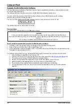
The compact flash socket of the EXIFU-A1 card can be used for either saving/re-loading the system 
configuration or upgrading the XN120 main unit’s firmware. 
 

Saving the system configuration 

You can save a copy of the customer configuration that can be re-loaded in the event of system failure. 
You will need a compact flash card with at least 4MByte of free capacity. 
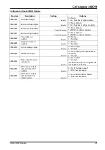
The XN120 will save the configuration in a folder named DATA on the flash card. If the flash card already has a 
DATA folder it will be overwritten each time the configuration is saved. 
 

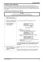
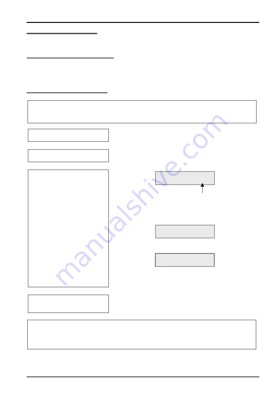
To save the customer configuration. 


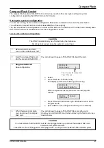
Remove the sub and main 
covers of the XN120 main unit. 


Insert the compact flash card 
into the socket on the EXIFU  

You do not need to power off the XN120 to insert the card. 


Program 90-03-01 

Save configuration. 


Ø 

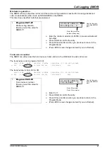
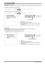
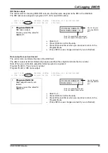
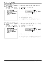
Enter 1. 

Ø 

Press HOLD to confirm the entry. 
The display will show the following while saving. 


When complete the display will show the next program 
number. 


Ø 

Press DC several times when you are done to return to the 
Program Mode. 

Ø 

(Press SPK to save changes and exit if you are finished). 


When the save is complete 
you can remove the compact 
flash card 

You do not need to power off the XN120 to remove the card. 
Unsure you hold the EXIFU card when removing the flash card – see 
caution below. 


CAUTION


You must ensure that the EXIFU card is not unplugged when you remove the compact flash card 

otherwise the system will reset. 

If the EXIFU card is unplugged DO NOT plug it back in until you have powered off the XN120 system. 

90-03-01    

Data Save      1  

Enter 1 to save the configuration 
Press DC to exit 


90-03-01    

SavingSystemData 


90-04-  M’tenanc 
Load Data 

CAUTION


The XN120 operation may be effected during the data save. 

Do not perform a save when the system is under load. 

Summary of Contents for EXIFU-A1

Page 1: ...0 main unit for further detail and Administrator User Guide Please keep all information supplied for future reference Regulatory Notice Refer to the Getting Started Guide 991409 5 supplied with the XN120 Main Unit for the Declaration of Conformity related to the product Warning This is a class A product In a domestic environment this product may cause radio interference in which case the user may ...

Page 2: ... to the Ethernet Cable 14 Maximum Cable Length 14 Serial Socket Call Logging SMDR 15 Which trunks will output to the call logger 15 Which telephones will output to the call logger 15 Enable the call logger output for the system 15 Set the Baudrate for the serial port 16 Sample SMDR Report 18 SMDR Output Options 20 Serial Cable 26 Compact Flash Socket 27 Saving the system configuration 27 System Re...

Page 3: ... EXIFU card can be installed The EXIFU A1 option card provides Ethernet port Expansion Unit Connections Serial RS232 port Compact Flash socket The EXIFU B1 option card provides Serial RS232 port System Connection Diagram XN120 EXIFU fits onto the base board of the XN120 main unit Serial Expansion Ethernet Compact Flash Socket Sockets Socket Socket ...

Page 4: ...120 EXIFU Guide Installation Procedure Unpack the EXIFU card Power off the XN120 and install the card You will also need to power off any expansion units if they are installed Power on the XN120 Test the EXIFU Configure the EXIFU ...

Page 5: ... The EXIFU A1 card will require LAN Cross Cable or LAN Straight cable connected to a hub for PC Programming Serial Null Modem Cable 9 pin female to 9 pin female for SMDR Compact Flash card for saving the system configuration upgrading the system software The EXIFU B1 card will require Serial Null Modem Cable 9 pin female to 9 pin female for SMDR ...

Page 6: ... also power off each XN120 expansion unit if you have any installed 2 Remove the sub cover and main cover of the XN120 unit that will have the card installed 3 Fit the EXIFU card The card is installed onto the connector CN2 on the right side of the base board within the XN120 main unit Ensure the connector is in line before pushing on the card 4 Refit the main cover and the sub cover Remove the br...

Page 7: ...tart Up Retain Customer Configuration This is the normal operation for powering the XN120 on Before you power on the system check that the NORMAL switch is set to ON This will ensure that the system memory retains your configuration The NORMAL switch is located to the right of the MOH Page connector on the main unit refer to the Getting Started Guide supplied with the XN120 for further information...

Page 8: ...Port section later in this guide 2 Test the Serial port See later in this guide for cable connections of the Serial socket You will need to connect the serial port of the XN120 to a COM port on your PC Connect via a null modem serial cable serial cross cable Set your COM port to the following Baud rate 19200 Data bits 8 Parity None Stop bits 1 Flow control None You will a Terminal Application eg W...

Page 9: ...3 none none Not Install 16 3 4 none none Not Install 17 3 5 none none Not Install 18 3 6 none none Not Install 3 Test the Expansion ports There is no specific method of testing the Expansion ports They can only be tested by connecting the XN120 expansion unit Refer to the separate guide supplied with the XN120 Expansion unit 4 Test the Compact Flash socket There is no specific method of testing th...

Page 10: ... exit configuration mode and test the changes Do not make all your changes at once as this can make testing very difficult Record your changes as you can only undo them by re entering the previous values Do not unplug the phone If it is unplugged by mistake then plug it back in wait for the display to show time and date and then press HOLD to return to the configuration mode Your changes will not ...

Page 11: ...e system phone to select the program item and change its value etc The LCD display will show the current program item the editing point is shown by a flashing curser SPK Save changes and exit configuration mode Numeric keys 1 to 9 and Alphanumeric entry keys Entered at the curser location HOLD Confirm the entry and step on to the next DC Step back one level Current entry is not confirmed DND CONF ...

Page 12: ...step on to the next if you did not make any changes to the entry Exiting Configuration Mode When you exit configuration mode your changes will be saved into the battery backed memory Until you exit any changes you have made are stored in temporary memory and will be lost if the power is switched off to the XN120 1 Press HOLD to confirm your current entry 2 Press DC several times 3 Press SPK When t...

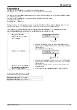
Page 13: ...ask for the XN120 this must be specified by the Network Administrator responsible for the customers LAN 1 Program 10 12 01 Enter the IP Address of the XN120 system Enter the Sub Net Mask You must power the XN120 system off on for the new IP address to take effect Ø Enter the IP Address you must enter three digits for each field Example 172 016 000 010 you do not need to enter the decimal points Ø ...

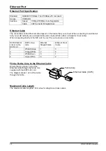
Page 14: ... a straight or cross cable When connecting directly to the NIC card in your PC you must use a cross cable RJ45 Ethernet socket on the EXIFU A1 RJ45 colour code Ethernet Straight Cable Ethernet Cross Cable 1 White Orange 1 3 2 Orange White 2 6 3 White Green 3 1 6 Green White 6 2 Fit the Ferrite Core to the Ethernet Cable Ensure that you make 1 turn of the Ethernet cable through the ferrite core sup...

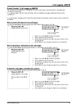
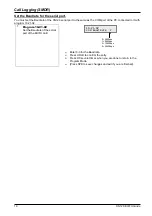
Page 15: ...le SMDR output for each telephone on the XN120 with program 15 01 03 1 Program 15 01 03 Enable SMDR for each telephone Ø Enter 1 to enable SMDR enter 0 to disable Ø Press HOLD to confirm the entry Ø Press DC several times when you are done to return to the Program Mode Ø Press SPK to save changes and exit if you are finished Enable the call logger output for the system You must enable SMDR output ...

Page 16: ...nnected to it with program 10 21 02 1 Program 10 21 02 Set the Baudrate of the serial port of the EXIFU card Ø Enter 0 3 for the Baudrate Ø Press HOLD to confirm the entry Ø Press DC several times when you are done to return to the Program Mode Ø Press SPK to save changes and exit if you are finished 10 21 02 COM Baud Rate 2 0 4800bps 1 9600bps 2 19200bps 3 38400bps ...

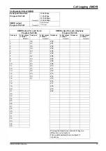
Page 17: ...unk port 0 Not output 1 Output Default 1 Trunk port 0 Not output 1 Output Default 1 Telephone 0 Not output 1 Output Default 1 Telephone 0 Not output 1 Output Default 1 1 36 200 2 37 201 3 38 202 4 39 203 5 40 204 6 41 205 7 42 206 8 43 207 9 44 208 10 45 209 11 46 210 12 47 211 13 48 212 14 49 213 15 50 214 16 51 215 17 216 18 217 19 218 20 219 21 220 22 23 24 25 26 27 28 29 30 31 32 33 34 35 Chan...

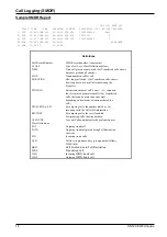
Page 18: ...or Transferred calls shows how long user was on call after answering the Transfer STATION Extension number of call owner i e extension that first placed or answered call For Transferred calls there can be more than one owner depending on how many extensions shared the call DIALLED No CLI For outgoing calls the number dialed or for incoming calls the Caller ID information RD COST For outgoing calls...

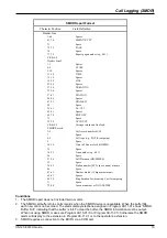
Page 19: ... Space 27 34 Call Duration HH MM SS 35 Space 36 45 Station number STA space nnnn or name 46 Space 47 61 Number dialed 15 digits maximum 62 63 Spaces 64 70 Ring duration for incoming Cost for outgoing 71 Space 72 80 Account number or NO ANSWER Conditions 1 The SMDR report does not include Intercom calls 2 The SMDR call buffer stores calls records when the SMDR device is unavailable When the buffer ...

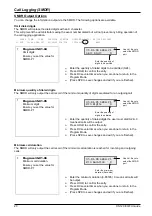
Page 20: ...oing call 1 Program 35 01 05 Minimum digits Ensure you set the value for SMDR P1 Ø Enter the quantity of dialed digits the user must dial 0 24 0 means all calls will be output Ø Press HOLD to confirm the entry Ø Press DC several times when you are done to return to the Program Mode Ø Press SPK to save changes and exit if you are finished Minimum call duration The SMDR will only output the call rec...

Page 21: ...runk name or trunk number in the LINE field for each call record The trunk name is set in program 14 01 01 CLASS TIME LINE DURATION STATION DIALLED No CLI RD COST ACCOUNT 01 POT 10 44 Line 001 00 00 30 STA 224 120392654XX 8841 The trunk number is from 001 to 051 CLASS TIME LINE DURATION STATION DIALLED No CLI RD COST ACCOUNT 01 POT 10 44 001 00 00 30 STA 224 120392654XX 8841 1 Program 35 02 03 Tru...

Page 22: ...to the Program Mode Ø Press SPK to save changes and exit if you are finished All Lines Busy The SMDR will output a call record each time a trunk group has all lines busy simultaneously The LINE field will show the trunk group number that is busy The DURATION field shows how long all lines were busy CLASS TIME LINE DURATION STATION DIALLED No CLI RD COST ACCOUNT 05 ALB 10 50 002 00 01 40 1 Program ...

Page 23: ...date is output as dd mm followed by a space and then three digits to indicate the line number Note When you enable date output the following options are ignored Program 35 02 03 Trunk name or number Program 35 02 12 DDI name output CLASS TIME LINE DURATION STATION DIALLED No CLI RD COST ACCOUNT 01 IVIN 10 44 09 03 001 00 00 30 STA 224 01765768691 1 Program 35 02 14 Date output for each call record...

Page 24: ...n output The call records for incoming ISDN DDI calls can show the DDI number instead of the line name or number in the LINE field CLASS TIME LINE DURATION STATION DIALLED No CLI RD COST ACCOUNT 01 IVIN 10 44 643111 00 00 30 STA 224 01765768691 1 Program 35 02 16 DDI number output instead of the line name number Ensure you set the value for SMDR P1 Ø Enter 0 or 1 Ø Press HOLD to confirm the entry ...

Page 25: ...nimum duration 35 02 03 Trunk name or number Default 1 0 Name 1 Number 35 02 09 Extension name or number Default 0 0 Name 1 Number 35 02 10 All Lines Busy output Default 0 0 Not output 1 Output 35 02 12 DDI Name output Default 0 0 Not output Line name number is output 1 Output 35 02 14 Date output for each call record Default 0 0 Not output 1 Output 35 02 03 35 02 12 are ignored if this option is ...

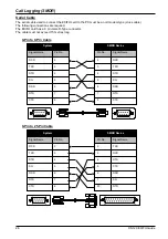
Page 26: ...le D Type connector The cable must not exceed 15 metres long 9 Pin to 9 Pin Cable 9 Pin to 25 Pin Cable Signal Name Pin No RXD TXD DTR SG DSR RTS CTS 2 3 4 5 6 7 8 Signal Name Pin No RXD TXD DTR SG DSR RTS CTS 2 3 4 5 6 7 8 Signal Name Pin No RXD TXD DTR SG DSR RTS CTS 2 3 4 5 6 7 8 Signal Name Pin No DTR TXD RXD RTS CTS DSR SG 20 2 3 4 5 6 7 SMDR Device System SMDR Device System 1 5 6 9 1 5 6 9 1...

Page 27: ...t the card 3 Program 90 03 01 Save configuration Ø Enter 1 Ø Press HOLD to confirm the entry The display will show the following while saving When complete the display will show the next program number Ø Press DC several times when you are done to return to the Program Mode Ø Press SPK to save changes and exit if you are finished 4 When the save is complete you can remove the compact flash card Yo...

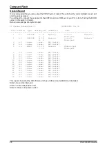
Page 28: ...308 9 16 Running Connect 4 6 Trunk port 3 1 3 none none Not Install 4 1 4 none none Not Install 5 1 5 BRIU 17 20 Running Station port 7 14 Trunk port 6 1 6 none none Not Install 7 2 1 none none Not Install 8 2 2 none none Not Install 9 2 3 none none Not Install 10 2 4 none none Not Install 11 2 5 none none Not Install 12 2 6 none none Not Install 13 3 1 none none Not Install 14 3 2 none none Not I...

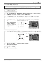
Page 29: ...1 Load configuration Ø Enter 1 Ø Press HOLD to confirm the entry The display will show the following while loading When complete the display will show the next program number Ø Press DC several times when you are done to return to the Program Mode Ø Press SPK to save changes and exit It may take a few minutes to save the configuration to memory Do not remove the flash card or power off the system ...

Page 30: ...AT The XN120 will not read the files if the compact flash card is formatted in another type e g FAT32 To build the compact flash card you will need the XN120 system software from the XN120 Technical CD 1 Insert the blank compact flash card into your PC 2 Insert the CD into your PC and from the main menu screen select the XN120 System Software link 3 You will see each version of XN120 software in s...

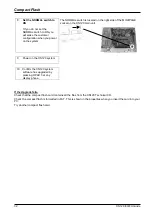
Page 31: ...ard inserted the system will not perform a cold start you will not erase the customer configuration The NORMAL switch is located on the right side of the MOH PAGE socket on the XN120 main unit 5 Power on the XN120 main unit The new system software will be copied from the compact flash card to the XN120 main unit Lamp LED4 will flash during the upgrade 6 When LED4 stops flashing power off the XN120...

Page 32: ... side of the MOH PAGE socket on the XN120 main unit 9 Power on the XN120 system 10 Confirm the XN120 system software has upgraded by pressing OPAC 3 at any display phone If the Upgrade fails Check that the compact flash card contains all the files from the XN120 Technical CD Check the compact flash is formatted in FAT This is shown in the properties when you insert the card into your PC Try anothe...

Page 33: ...Expansion Socket XN120 EXIFU Guide 33 Expansion Socket Refer to the guide supplied with the expansion unit ...

Reviews: