DIAGNOSTIC MANUAL
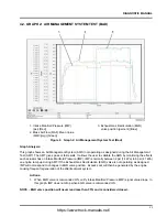
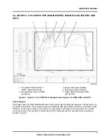
4.2. GRAPH 2: AIR MANAGEMENT SYSTEM TEST (BAD)
1. Intake Manifold Pressure (IMP)
(psi) [Red]
2. Mass Air Flow (MAF) Mean Value
(MMV)(mg) [Green]
3. Exhaust Gas Recirculation (EGR)
valve position (percent) [Blue]
Figure 6
Graph 2: Air Management System Test (Bad)
Graph Analysis:
This graph shows an Air Management System (AMS) not operating as designed during the Air Management
Test (AMT). The AMT gives pass or fail results. It allows the user to validate the AMS by monitoring the effects
each actuator has on Intake Manifold Pressure (IMP). IMP is normally between 2 psi (14 kPa) to 6 psi (41 kPa)
on engine ramp up during AMT. If the Exhaust Gas Recirculation (EGR) valve is not operating as designed,
IMP will not respond to changes in EGR valve position. Excess soot will then be generated by the engine
causing frequent regeneration of the aftertreatment system.
Actions:
1.
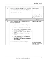
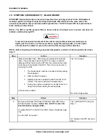
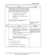
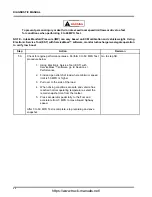
When EGR valve is commanded ON, verify Intake Manifold Pressure (IMP) signal value drops. In
this graph, IMP does not drop when EGR valve is commanded ON.
NOTE – EGR valve position will never read less than 35% and is considered closed.
53
https://www.truck-manuals.net/

