background image

DIAGNOSTIC MANUAL

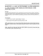
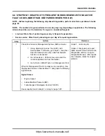
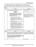
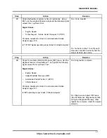
WARNING

To prevent personal injury or death, do not exceed local speed limit laws or drive too fast
for conditions when performing Lug Down Test.

Step

Action

Decision

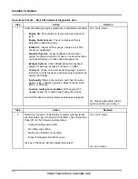
2A

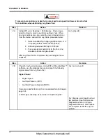
Using EST, go to Sessions > Performance. Find an open
stretch of road in order to perform Lug Down Test. When
driving conditions are safe, select the record snapshot icon
from the toolbar, and perform Lug Down procedure below:

1.

Select a suitable high range gear (Example: In a
10 speed gearbox, select the 8th speed).

2.

Allow engine speed to drop to 1000 rpm.

3.

Press accelerator pedal fully to the floor, and
accelerate to rated engine speed.

After Lug Down Test is complete, stop recording and save
snapshot.

Go to step 2B

Step

Action

Decision

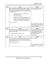
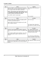
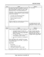
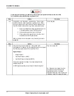
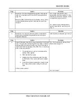
2B

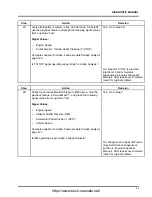
Check for low fuel rail pressure. Using EST with ServiceMaxx™
software, use the playback feature and graph the following
signal values from Lug Down Test:

Signal Values:

Engine Speed

Fuel Rail Pressure (FRP)

Fuel Rail Pressure Desired (FRPD)

Compare snapshot to Graph 3 and associated Graph Analysis
page 124.

Is FRP signal operating as per Graph 3 Graph Analysis?

Yes: Go to step 2C

No: Diagnose and repair low fuel
rail pressure (See Performance
Diagnostics section in Engine
Diagnostic Manual). After repairs
are complete, retest for original
problem.

84

https://www.truck-manuals.net/

Summary of Contents for MaxxForce DT

Page 1: ...Revision 5 EPA 10 US Canada October 2014 DIAGNOSTIC MANUAL Aftertreatment Symptom Based Diagnostic and Inspection Manual MaxxForce DT 9 and 10 EPA 10 MaxxForce 11 13 and 15 EPA 10 Navistar Inc 2701 Na...

Page 2: ...https www truck manuals net...

Page 3: ...5 GRAPH 5 NORMAL EXHAUST GAS TEMPERATURES EFFICIENT DOC AND UNRESTRICTED AFI 57 4 6 GRAPH 6 ERRATIC EXHAUST GAS TEMPERATURES 59 4 7 GRAPH 7 LOW EXHAUST GAS TEMPERATURES RESTRICTED AFI 60 4 8 SOOT LOAD...

Page 4: ...14 1 MAXXFORCE 11 13 AND 15 151 15 REGEN INHIBITORS AND ENTRY CONDITIONS 152 15 1 REGEN INHIBITORS 152 15 2 ENTRY CONDITIONS 156 16 DPF AND DOC REUSE GUIDELINES 159 16 1 MAXXFORCE DT 9 AND 10 MAXXFOR...

Page 5: ...vances Procedures specifications and parts defined in published technical service literature may be altered Technical service literature is revised periodically If a technical publication is ordered t...

Page 6: ...ion and Note Warning A warning describes actions necessary to prevent or eliminate conditions hazards and unsafe practices that can cause personal injury or death Caution A caution describes actions n...

Page 7: ...before removing panels housing covers and caps If an engine or vehicle is not safe to operate tag the ignition key Fire Prevention Make sure charged fire extinguishers are in the work area NOTE Check...

Page 8: ...ssure Follow approved procedures only Fuel Do not over fill the fuel tank Overfill creates a fire hazard Do not smoke in the work area Do not refuel the tank when the engine is running Removal of Tool...

Page 9: ...m Operational Checks Operational Checks Start Aftertreatment Diagnostics Here Step Action Decision 1 Verify the following engine systems are in satisfactory condition Engine Oil Park vehicle on level...

Page 10: ...cracks or internal damage without removing the DPF from the vehicle and is used to test basic functionality of the diesel particulate filter This is to be done prior to removing the DPF 1 The transmi...

Page 11: ...om 2 Medium Duty Engine No Start Starts and Stalls page 17 Step Action Decision 5 Using Electronic Service Tool EST with ServiceMaxx software check Diagnostic Trouble Code DTC list for SPN 3719 FMI 0...

Page 12: ...ad Test Specific Session and verify Load Test Specific Session is unchecked 2 Go to Sessions Performance and select the record snapshot icon from the toolbar 3 Go to Tests KOER Tests Air Management Te...

Page 13: ...cision 2A Check for engine performance issues Perform 0 to 60 MPH Test procedure below 1 Using EST go to Sessions Performance 2 Find an open stretch of road where minimum speed limit is 50 mph or high...

Page 14: ...Signal Values ICP desired ICP Injection Pressure Regulator IPR valve control Compare snapshot to Graph 3 and associated Graph Analysis page 54 Is ICP system operating as per Graph 3 Graph Analysis Yes...

Page 15: ...ne Speed Engine Load Intake Manifold Pressure IMP Exhaust Back Pressure EBP Accelerator Pedal Position 1 APP1 Compare snapshot to Graph 4 and associated Graph Analysis page 55 Is AMS operating as per...

Page 16: ...nlet Temperature DPFIT Diesel Particulate Filter Outlet Temperature DPFOT DPF Soot Load Compare snapshot to Graph 5 6 and 7 page 57 Which graph does snapshot most closely match Graph 5 Diagnostics com...

Page 17: ...F DOC and PDOC reusable Yes Install removed aftertreatment system components and go to step 6 No Replace failed component s After repairs are complete go to step 6 Step Action Decision 6 Determine roo...

Page 18: ...ctor AFI replacement Perform Aftertreatment Fuel Injector AFI visual inspection Remove AFI See Engine Service Manual and check for the following Visual Checks Correct AFI gasket is installed Figure 1...

Page 19: ...ion 10 Verify exhaust gas temperatures are within specification 1 Using Electronic Service Tool EST with ServiceMaxx software go to Tests KOER Aftertreatment Tests Onboard Filter Cleanliness Test OBFC...

Page 20: ...epairs 1 Verify engine coolant temperature is greater than 180 F 82 C and lube oil temperature is greater than 176 F 80 C 2 Using EST with ServiceMaxx software go to Tests and deselect Load Test Speci...

Page 21: ...gine does not start wait 2 to 3 minutes and crank engine again for a maximum of 20 seconds 5 Stop recording 6 Use the playback feature in ServiceMaxx and graph TC1TOP and Diesel Particulate Filter Dif...

Page 22: ...his is normal and the DPF should NOT be replaced Is the DPF contaminated Yes Remove Pre Diesel Oxidation Catalyst PDOC Diesel Oxidation Catalyst DOC and then and then go to step 4 No Go to step 5 Step...

Page 23: ...tertreatment system components and then go to step 7 Step Action Decision 6 Determine root cause of exhaust system contamination See Engine Symptoms Diagnostics section in Engine Diagnostic Manual Aft...

Page 24: ...or clamp After repairs are complete go to step 9 Step Action Decision 9 Check for a failed Air Management System AMS actuator 1 Using EST with ServiceMaxx software go to Tests Load Test Specific Sessi...

Page 25: ...sion 10A Check for engine performance issues Perform 0 to 60 MPH Test procedure below 1 Using EST go to Sessions Performance 2 Find an open stretch of road where minimum speed limit is 50 mph or highe...

Page 26: ...tion in Engine Diagnostic Manual After repairs are complete retest for original problem Step Action Decision 10C Check for Air Management System AMS issue Using EST with ServiceMaxx software use the p...

Page 27: ...repairs 1 Verify engine coolant temperature is greater than 180 F 82 C and lube oil temperature is greater than 176 F 80 C 2 Using EST with ServiceMaxx software go to Tests and deselect Load Test Spec...

Page 28: ...g Electronic Service Tool EST with ServiceMaxx software check Diagnostic Trouble Code DTC list to determine which of the following fault codes is active SPN 3719 3936 FMI 0 15 or 16 Which fault code i...

Page 29: ...es go to Step 11 Step Action Decision 4 Do three Onboard Filter Cleanliness Tests OBFCT to decrease soot load of Diesel Particulate Filter DPF Using EST go to Tests KOER Aftertreatment Tests Onboard F...

Page 30: ...ymptom 5 Medium Duty Black smoke page 44 No Go to step 11 Step Action Decision 7 Determine if Diesel Particulate Filter DPF Pre Diesel Oxidation Catalyst PDOC and Diesel Oxidation Catalyst DOC are con...

Page 31: ...to step 11 Step Action Decision 11 Check for a failed Air Management System AMS actuator 1 Using EST with ServiceMaxx software go to Tests Load Test Specific Session and verify Load Test Specific Sess...

Page 32: ...cision 11A Check for engine performance issues Perform 0 to 60 MPH Test procedure below 1 Using EST go to Sessions Performance 2 Find an open stretch of road which will safely allow full acceleration...

Page 33: ...tion in Engine Diagnostic Manual After repairs are complete retest for original problem Step Action Decision 11C Check for Air Management System AMS issue Using EST with ServiceMaxx software use the p...

Page 34: ...from the toolbar When OBFCT is complete stop recording Use the playback feature and graph the following signal values from OBFCT Signal Values Diesel Oxidation Catalyst Inlet Temperature DOCIT Diesel...

Page 35: ...ctor AFI replacement Perform Aftertreatment Fuel Injector AFI visual inspection Remove AFI see Engine Service Manual and check for the following Visual Checks Correct AFI gasket is installed Figure 2...

Page 36: ...rtreatment Tests Onboard Filter Cleanliness Test OBFCT 2 Go to Sessions Performance and select the record snapshot icon from the toolbar When OBFCT is complete stop recording Use the playback feature...

Page 37: ...for system repairs 1 Verify engine coolant temperature is greater than 180 F 82 C and lube oil temperature is greater than 176 F 80 C 2 Using EST with ServiceMaxx software go to Tests and deselect Lo...

Page 38: ...2 Step Action Decision 2 Using Electronic Service Tool EST with ServiceMaxx software check Diagnostic Trouble Code DTC list to determine which of the following fault codes is active SPN 3719 FMI 0 15...

Page 39: ...de go to Step 11 Step Action Decision 5 Do three Onboard Filter Cleanliness Tests OBFCT to decrease soot load of Diesel Particulate Filter DPF Using EST go to Tests KOER Aftertreatment Tests Onboard F...

Page 40: ...mptom 5 Medium Duty Black smoke page 44 No Go to step 12 Step Action Decision 8 Determine if Diesel Particulate Filter DPF Pre Diesel Oxidation Catalyst PDOC and Diesel Oxidation Catalyst DOC are cont...

Page 41: ...o step 12 Step Action Decision 12 Check for a failed Air Management System AMS actuator 1 Using EST with ServiceMaxx software go to Tests Load Test Specific Session and verify Load Test Specific Sessi...

Page 42: ...sion 12A Check for engine performance issues Perform 0 to 60 MPH Test procedure below 1 Using EST go to Sessions Performance 2 Find an open stretch of road where minimum speed limit is 50 mph or highe...

Page 43: ...tion in Engine Diagnostic Manual After repairs are complete retest for original problem Step Action Decision 12C Check for Air Management System AMS issue Using EST with ServiceMaxx software use the p...

Page 44: ...eanliness Test When OBFCT is complete stop recording Use the playback feature and graph the following signal values from OBFCT Signal Values Diesel Oxidation Catalyst Inlet Temperature DOCIT Diesel Pa...

Page 45: ...ctor AFI replacement Perform Aftertreatment Fuel Injector AFI visual inspection Remove AFI see Engine Service Manual and check for the following Visual Checks Correct AFI gasket is installed Figure 4...

Page 46: ...reatment Tests Onboard Filter Cleanliness Test OBFCT 2 Go to Sessions Performance and select the record snapshot icon from the toolbar When OBFCT is complete stop recording Use the playback feature an...

Page 47: ...epairs 1 Verify engine coolant temperature is greater than 180 F 82 C and lube oil temperature is greater than 176 F 80 C 2 Using EST with ServiceMaxx software go to Tests and deselect Load Test Speci...

Page 48: ...ll vehicle operational checks page 5 Step Action Decision 1 Diesel Particulate Filter DPF Snap Acceleration Test Quick Test This procedure checks the DPF for cracks or internal damage without removing...

Page 49: ...and loose parts End of diagnostics Step Action Decision 4 Check for a Failed Air Management System AMS actuator 1 Using an Electronic Service Tool EST with ServiceMaxx software go to Tests Load Test...

Page 50: ...performance issues Perform 0 to 60 MPH Test procedure below 1 Using Electronic Service Tool EST with ServiceMaxx software go to Sessions Performance 2 Find an open stretch of road where minimum speed...

Page 51: ...nostics section in Engine Diagnostic Manual After repairs are complete go to Step 10A Step Action Decision 5C Check for Air Management System AMS issue On the Electronic Service Tool EST with ServiceM...

Page 52: ...board Filter Cleanliness Test When OBFCT is complete stop recording Use the playback feature and graph the following signal values from OBFCT Diesel Oxidation Catalyst Inlet Temperature DOCIT Diesel P...

Page 53: ...ertreatment Fuel Injector AFI visual inspection Remove the AFI doser housing from the turbo outlet pipe see Engine Service Manual and perform the following visual checks Correct AFI gasket is installe...

Page 54: ...are complete go to step 10 No Go to step 10 Step Action Decision 10 Verify exhaust gas temperatures are within specification 1 Using Electronic Service Tool EST with ServiceMaxx software go to Tests...

Page 55: ...Red 3 Exhaust Gas Recirculation EGR valve position percent Purple Figure 5 Graph 1 Air Management System Test Good Graph Analysis This graph shows normal operation of the Air Management System AMS du...

Page 56: ...a stabilized high point and a stabilized low point then compare to the table below Engine MAF Mean Value MMV Difference Tolerance MaxxForce DT 215 230 HP 690 1000 Less than 690 Fails AMS Test MaxxFor...

Page 57: ...itoring the effects each actuator has on Intake Manifold Pressure IMP IMP is normally between 2 psi 14 kPa to 6 psi 41 kPa on engine ramp up during AMT If the Exhaust Gas Recirculation EGR valve is no...

Page 58: ...oes not give pass or fail results It only allows the user to validate ICP and Injection Control Pressure Desired ICPD signal values under load As engine rpm increases ICP should steadily increase Low...

Page 59: ...peed Engine Load IMP EBP and APP1 Graph Analysis This graph shows the Intake Manifold Pressure IMP signal value operating as designed This test does not give pass or fail results It only allows the us...

Page 60: ...0 rpm 2 Verify Exhaust Back Pressure EBP is less than 70 psi 414 kPa with APP1 signal value at 99 6 and engine speed between 1800 rpm to 2200 rpm NOTE IMP signal value may be as low as 29 psi 221 kPa...

Page 61: ...r Inlet Temperature DPFIT degrees Fahrenheit Blue 3 Diesel Particulate Filter Outlet Temperature DPFOT degrees Fahrenheit Green Figure 9 Graph 5 Normal Exhaust Gas Temperatures Efficient DOC AND Unres...

Page 62: ...at approximate target temperature for current soot load level See Soot Load Level vs Exhaust Gas Target Temperature Chart page 62 2 Verify Diesel Oxidation Catalyst Inlet Temperature DOCIT signal valu...

Page 63: ...m occur when the Diesel Oxidation Catalyst becomes contaminated or an issue with the Aftertreatment Fuel Injector AFI is present This test does not give pass or fail results It only allows the user to...

Page 64: ...erature DPFOT degrees Fahrenheit Green Figure 11 Graph 7 Low Exhaust Gas Temperatures Restricted AFI Graph Analysis This graph shows low exhaust gas temperatures indicating a restricted Aftertreatment...

Page 65: ...at approximate target temperature for current soot load level See Soot Load Level vs Exhaust Gas Target Temperature Chart page 62 2 Verify Diesel Oxidation Catalyst Inlet Temperature DOCIT signal val...

Page 66: ...49 2 1090 F 588 C 50 66 3 1075 F 579 C 67 83 4 1050 F 566 C 84 99 5 1025 F 552 C 100 116 6 1000 F 538 C 117 132 7 975 F 524 C 133 149 8 900 F 482 C 150 169 9 860 F 460 C 170 184 10 850 F 454 C 185 19...

Page 67: ...Diesel Oxidation Catalyst Outlet Temperature DOCOT and Diesel Particulate Filter Outlet Temperature DPFOT Monitors Diesel Particulate Filter Differential Pressure DPFDP Controls engine operating param...

Page 68: ...ke Vehicle Speed Sensor VSS Driveline Disconnect Switch DDS Power Take Off Switch PTO Diesel Oxidation Catalyst DOC Diesel Particulate Filter DPF Diesel Oxidation Catalyst Outlet Temperature DOCOT sen...

Page 69: ...ETV Warning Indicators Inlet Air Heater IAH Aftertreatment Control Module ACM Aftertreatment Fuel Inlet Sensor AFTFIS Aftertreatment Fuel Pressure 2 AFTFP2 sensor Aftertreatment Fuel Shutoff Valve AFT...

Page 70: ...Oxidizes hydrocarbons and carbon monoxide CO in exhaust stream Provides heat for exhaust system warm up Diesel Particulate Filter DPF The DPF does the following Captures and temporarily stores carbon...

Page 71: ...he clean side of the low pressure fuel system and will provide a metered amount of fuel to the Aftertreatment Fuel Injector AFI The DSI unit provides pressurized fuel injection pulses to the AFI The A...

Page 72: ...he Engine Control Module ECM monitors and controls engine operation to ensure maximum performance and adherence to emissions standards The ECM performs the following functions Provide reference voltag...

Page 73: ...e s air intake path through the CAC to help heat the exhaust aftertreatment during regeneration and to assist when heavy EGR is requested The electronic portion of the ETV contains a microprocessor th...

Page 74: ...ure Valve EBPV The Exhaust Back Pressure Valve EBPV controls the position of the exhaust valve increasing or decreasing exhaust gas back pressure and temperature to allow the Diesel Oxidation Catalyst...

Page 75: ...System MaxxForce DT 9 and 10 Engines Exhaust Gas Recirculation EGR Valve The EGR valve receives the desired valve position from the ECM for exhaust gas recirculation The EGR valve regulates the flow o...

Page 76: ...improve exhaust emissions Allows for more efficient operation of the aftertreatment system 1 PDOC back bracket attaches to engine 2 PDOC bracket 3 Exhaust Flange Gasket 4 11 x 20 x 24 mm spacer 3 5 M...

Page 77: ...ly 11 Low pressure turbine outlet 12 High pressure compressor housing 13 High pressure turbine inlet 14 Low pressure turbine housing 15 Low pressure bearing housing 16 Low pressure compressor housing...

Page 78: ...ides high charge air pressure to improve engine performance and to help reduce emissions Exhaust gas flow The HP turbocharger is connected directly to the exhaust manifold through the HP turbine inlet...

Page 79: ...4 DPFOT signal Out of Range LOW DPFOT signal circuit short to GND Failed DPFOT sensor 3246 7 DPFOT not warming along with engine Biased DPFOT circuit or sensor 3246 20 DPF over temperature possible f...

Page 80: ...t OPEN or short to PWR Failed AFTFIS 3480 4 AFTFP1 signal Out of Range LOW AFTFP1 signal circuit short to GND Failed AFTFIS 3482 3 AFT Fuel Shutoff Valve short to PWR AFTFSV circuit OPEN or short to P...

Page 81: ...EN or short to PWR SIG GND circuit OPEN Failed DPFOT sensor 4765 4 DOCIT signal Out of Range LOW DOCIT signal circuit short to GND Failed DPFOT sensor 4765 7 DOCIT not increasing with engine temperatu...

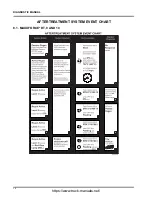
Page 82: ...DIAGNOSTIC MANUAL AFTERTREATMENT SYSTEM EVENT CHART 8 1 MAXXFORCE DT 9 AND 10 78 https www truck manuals net...

Page 83: ...ystem These illuminated warning lamps may indicate an engine mechanical or performance concern Tools Required Electronic Service Tool EST with ServiceMaxx software Interface cable RP1210B compliant su...

Page 84: ...l fuel gauge look into fuel tanks to verify fuel level and make sure fuel levels are equal in both tanks Fuel quality Obtain a fuel sample and check for water waxing icing sediment gasoline Diesel Exh...

Page 85: ...e 113 No Go to Symptom 1 Heavy Duty Frequent Parked Regens with No Active Codes More than one parked regen per day page 83 Step Action Decision 4 Using Electronic Service Tool EST with ServiceMaxx sof...

Page 86: ...c Trouble Code DTC list for SPN 3719 FMI 0 or 16 DPF Soot Load Is SPN 3719 FMI 0 or SPN 3719 FMI 16 the only fault code s active Yes Go to Symptom 3 Heavy Duty SPN 3719 Active Only or Frequent Regens...

Page 87: ...ement System AMS actuator 1 Using Electronic Service Tool EST with ServiceMaxx software go to Tests Load Test Specific Session and verify Load Test Specific Session is unchecked 2 Go to Sessions Perfo...

Page 88: ...celerator pedal fully to the floor and accelerate to rated engine speed After Lug Down Test is complete stop recording and save snapshot Go to step 2B Step Action Decision 2B Check for low fuel rail p...

Page 89: ...n Engine Diagnostic Manual After repairs are complete retest for original problem Step Action Decision 2D Check for an Intake Manifold Pressure IMP issue Use the playback feature in ServiceMaxx and gr...

Page 90: ...closely match Graph 6 Diagnostics complete Graph 7 Go to step 4 Graph 8 Go to step 7 Step Action Decision 4 Determine if DPF or DOC is contaminated Remove the DPF and DOC see Exhaust System Service M...

Page 91: ...Let the engine idle for 5 minutes while monitoring O2S Temperature signal value Is O2S Temperature signal value greater than 1400 F 760 C Yes Go to step 8 No Repair O2S or circuit See Electronic Contr...

Page 92: ...tor AFI replacement Perform Aftertreatment Fuel Injector AFI visual inspection Remove AFI see Engine Service Manual and check for the following Visual Checks Correct AFI gasket is installed Figure 22...

Page 93: ...Step Action Decision 12 Verify exhaust gas temperatures are within specification 1 Using Electronic Service Tool EST with ServiceMaxx software go to Sessions Performance and select the record snapsho...

Page 94: ...een diagnosed and repaired Has root cause for frequent regens been diagnosed and repaired Yes Diagnostics complete No Go back to step 1 of Engine and Aftertreatment System Operational Checks page 80 t...

Page 95: ...articulate Filter Differential Pressure DPFDP signal values 5 Verify DPFDP and TC1TOP are within specification DPFDP signal value should be less than 1 psi 7 kPa and TC1TOP signal value should be less...

Page 96: ...are the DPF DOC and PDOC reusable Yes Go to step 6 No Replace failed component s After repairs are complete go to step 6 Step Action Decision 5 Determine if removed aftertreatment system components ne...

Page 97: ...r clamp After repairs are complete go to step 8 Step Action Decision 8 Check for a failed Air Management System AMS actuator 1 Using Electronic Service Tool EST with ServiceMaxx software go to Tests L...

Page 98: ...celerator pedal fully to the floor and accelerate to rated engine speed After Lug Down Test is complete stop recording and save snapshot Go to step 9B Step Action Decision 9B Check for low fuel rail p...

Page 99: ...completed correctly and the proper decision was made Step Action Decision 9D Check for an Intake Manifold Pressure IMP issue Use the playback feature in ServiceMaxx and graph the following signal valu...

Page 100: ...bar Then go to Tests KOER Aftertreatment Tests Onboard Filter Cleanliness Test Is SPN 3719 still active after OBFCT is complete Yes Go to step 2 No Go to step 6 Step Action Decision 2 Determine if Die...

Page 101: ...s section in Engine Diagnostic Manual After repairs are complete go to step 7 Step Action Decision 6 Diesel Particulate Filter DPF Snap Acceleration Test Quick Test This procedure checks the DPF for c...

Page 102: ...Go to Tests KOER Tests Air Management Test When Air Management Test is complete stop recording Use the playback feature in ServiceMaxx and graph the following signal values Signal Values Engine Speed...

Page 103: ...celerator pedal fully to the floor and accelerate to rated engine speed After Lug Down Test is complete stop recording and save snapshot Go to step 8B Step Action Decision 8B Check for low fuel rail p...

Page 104: ...n Engine Diagnostic Manual After repairs are complete retest for original problem Step Action Decision 8D Check for an Intake Manifold Pressure IMP issue Use the playback feature in ServiceMaxx and gr...

Page 105: ...o step 10 Step Action Decision 10 Check Oxygen Sensor O2S operation Start the engine and allow to reach normal operating temperature Using EST with ServiceMaxx software go to Sessions Performance Let...

Page 106: ...r AFI replacement Perform Aftertreatment Fuel Injector AFI visual inspection Remove AFI see Engine Service Manual and check for the following Visual Checks Correct AFI gasket is installed Figure 23 AF...

Page 107: ...ce and select the record snapshot icon from the toolbar 2 Go to Tests KOER Aftertreatment Tests Onboard Filter Cleanliness Test When OBFCT is complete stop recording Use the playback feature and graph...

Page 108: ...snapshot icon from the toolbar Then go to Tests KOER Aftertreatment Tests Onboard Filter Cleanliness Test Is SPN 3719 still active after OBFCT is complete Yes Go to step 3 No Go to step 7 Step Action...

Page 109: ...ection in Engine Diagnostic Manual After repairs are complete go to step 8 Step Action Decision 7 Diesel Particulate Filter DPF Snap Acceleration Test Quick Test This procedure checks the DPF for crac...

Page 110: ...o to Tests KOER Tests Air Management Test When Air Management Test is complete stop recording Use the playback feature in ServiceMaxx and graph the following signal values Signal Values Engine Speed I...

Page 111: ...celerator pedal fully to the floor and accelerate to rated engine speed After Lug Down Test is complete stop recording and save snapshot Go to step 9B Step Action Decision 9B Check for low Fuel Rail P...

Page 112: ...Engine Diagnostic Manual After repairs are complete retest for original problem Step Action Decision 9D Check for an Intake Manifold Pressure IMP issue Use the playback feature in ServiceMaxx and gra...

Page 113: ...to step 11 Step Action Decision 11 Check Oxygen Sensor O2S operation Start the engine and allow to reach normal operating temperature Using EST with ServiceMaxx software go to Sessions Performance Let...

Page 114: ...tor AFI replacement Perform Aftertreatment Fuel Injector AFI visual inspection Remove AFI see Engine Service Manual and check for the following Visual Checks Correct AFI gasket is installed Figure 24...

Page 115: ...Action Decision 16 Verify exhaust gas temperatures are within specification 1 Using Electronic Service Tool EST with ServiceMaxx software go to Sessions Performance and select the record snapshot icon...

Page 116: ...egens symptom Has root cause for frequent regens been diagnosed and repaired Yes Diagnostics complete No Go back to step 1 of Engine and Aftertreatment System Operational Checks page 80 to verify engi...

Page 117: ...off and chock the wheels to prevent vehicle from moving in either direction NOTE Before beginning the following step based diagnostics perform all vehicle operational checks page 80 Step Action Decisi...

Page 118: ...fault code s Using Electronic Service Tool EST with ServiceMaxx software go to Tests KOER Aftertreatment Tests Onboard Filter Cleanliness Test While OBFCT is running check the following components fo...

Page 119: ...repair failed actuator See Performance Diagnostics section in Engine Diagnostic Manual After repairs are complete retest for original problem WARNING To prevent personal injury or death do not exceed...

Page 120: ...cs section in Engine Diagnostic Manual After repairs are complete retest for original problem Step Action Decision 5C Verify aftertreatment system is free of restrictions Using Electronic Service Tool...

Page 121: ...roblem Step Action Decision 6 Verify exhaust gas temperatures are within specification 1 Using Electronic Service Tool EST with ServiceMaxx software go to Sessions Performance and select the record sn...

Page 122: ...eplacement Perform Aftertreatment Fuel Injector AFI visual inspection Remove AFI See Engine Service Manual and check for the following Visual Checks Correct AFI gasket is installed Figure 25 AFI and b...

Page 123: ...tep Action Decision 10 Verify exhaust gas temperatures are within specification 1 Using Electronic Service Tool EST with ServiceMaxx software go to Tests KOER Aftertreatment Tests Onboard Filter Clean...

Page 124: ...alysis This graph shows normal operation of the Air Management System AMS during the Air Management Test AMT The AMT does not give pass or fail results It only allows the user to validate the AMS by m...

Page 125: ...lue drops NOTE MaxxForce 11 ONLY AFT regen status stays Not Active NOTE Turbocharger 1 Wastegate Control TC1WC does not affect engine performance and is removed from post production engines If engine...

Page 126: ...agement Test AMT The AMT does not give pass or fail results It only allows the user to validate the AMS by monitoring the effects each actuator has on Intake Manifold Pressure IMP sensor IMP is normal...

Page 127: ...aph IMP does not drop when TC2WC is commanded ON NOTE MaxxForce 11 ONLY AFT regen status stays Not Active NOTE Turbocharger 1 Wastegate Control TC1WC does not affect engine performance and is removed...

Page 128: ...RP and FRPD Graph Analysis This graph shows a fuel management system operating as designed This test does not give pass or fail results It only allows the user to validate Fuel Rail Pressure FRP and F...

Page 129: ...i 219 943 kPa at full load 2 Verify FRP signal value is within a 1000 psi 6 895 kPa range of FRPD signal value during acceleration NOTE Analyze Lug Down Test signal values only during engine accelerat...

Page 130: ...rating as designed unrestricted This test does not give pass or fail results It only allows the user to validate Turbocharger 1 Turbine Outlet Pressure TC1TOP signal value under load High TC1TOP will...

Page 131: ...gned This test does not give pass or fail results It only allows the user to validate IMP signal value under load Engine power band is typically between 1300 to 1700 rpm with peak power occurring arou...

Page 132: ...kPa to 43 psi 296 kPa with Accelerator Pedal Position 1 APP1 signal value at 99 6 and engine speed between 1300 rpm to 1700 rpm NOTE Analyze Lug Down Test signal values only during engine acceleration...

Page 133: ...en 4 Diesel Oxidation Catalyst DOC at operating temperature and stabilized 5 Diesel Oxidation Catalyst Inlet Temperature DOCIT degrees Fahrenheit Purple Figure 31 Graph 6 Normal Exhaust Gas Temperatur...

Page 134: ...Diesel Particulate Filter Outlet Temperature DPFOT signal values are greater than 900 F 482 C 2 Verify Diesel Oxidation Catalyst Inlet Temperature DOCIT signal value is between 550 F 287 C to 800 F 4...

Page 135: ...Inefficient DOC Graph Analysis This graph shows inverted exhaust gas temperatures indicating an inefficient Diesel Oxidation Catalyst DOC Inverted temperatures in the exhaust stream occur when the Die...

Page 136: ...OCOT indicating inverted exhaust gas temperatures 2 Verify Diesel Oxidation Catalyst Inlet Temperature DOCIT signal value is between 550 F 287 C to 800 F 427 C NOTE It is normal to see Diesel Oxidatio...

Page 137: ...ted AFI Graph Analysis This graph shows low exhaust gas temperatures indicating a restricted Aftertreatment Fuel Injector AFI Low temperatures in the exhaust stream occur when Diesel Oxidation Catalys...

Page 138: ...F 482 C In this graph DOCOT and DPFOT are less than 900 F 482 C 2 Verify Diesel Oxidation Catalyst Inlet Temperature DOCIT signal value is between 550 F 287 C to 800 F 427 C NOTE It is normal to see...

Page 139: ...Diesel Oxidation Catalyst Outlet Temperature DOCOT and Diesel Particulate Filter Outlet Temperature DPFOT Monitors Diesel Particulate Filter Differential Pressure DPFDP Controls engine operating para...

Page 140: ...l Position APP sensor Park brake Vehicle Speed Sensor VSS Driveline Disconnect Switch DDS Power Take Off Switch PTO Diesel Oxidation Catalyst DOC Diesel Particulate Filter DPF Diesel Oxidation Catalys...

Page 141: ...Valve ETV Warning Indicators Inlet Air Heater IAH Aftertreatment Fuel Inlet Sensor AFTFIS Aftertreatment Fuel Pressure 2 AFTFP2 sensor Aftertreatment Fuel Shutoff Valve AFTFSV Aftertreatment Fuel Dose...

Page 142: ...the Low Pressure LP turbocharger wastegate control port High Pressure HP turbocharger wastegate control port the Exhaust Back Pressure Valve EBPV control port and the Turbocharger 1 Turbine Outlet Pre...

Page 143: ...zes hydrocarbons and carbon monoxide CO in exhaust stream Provides heat for exhaust system warm up Diesel Particulate Filter DPF The DPF does the following Captures and temporarily stores carbon based...

Page 144: ...e 11 and 13 Engines Downstream Injection DSI Unit The DSI unit is connected to the clean side of the low pressure fuel system and will provide a metered amount of fuel to the AFI The DSI unit provides...

Page 145: ...ECM 96 pin E1 terminal Figure 38 ECM MaxxForce 11 and 13 Engines Engine Control Module ECM The Engine Control Module ECM monitors and controls engine operation to ensure maximum performance and adher...

Page 146: ...s air intake path through the CAC to help heat the exhaust aftertreatment during regeneration and to assist when heavy EGR is requested The electronic portion of the ETV contains a microprocessor tha...

Page 147: ...Typical Exhaust Back Pressure Valve EBPV The Exhaust Back Pressure Valve EBPV controls the position of the exhaust valve increasing or decreasing exhaust gas back pressure and temperature to allow the...

Page 148: ...on MaxxForce 11 and 13 Engines Right Rear Engine Exhaust Gas Recirculation EGR Valve The EGR valve receives the desired valve position from the ECM for exhaust gas recirculation The EGR valve regulate...

Page 149: ...improve exhaust emissions Allows for more efficient operation of the aftertreatment system 1 PDOC back bracket attaches to engine 2 PDOC bracket 3 Exhaust Flange Gasket 4 11 x 20 x 24 mm spacer 3 5 M1...

Page 150: ...ght side of the engine Intake air flow Filtered air enters the LP compressor where it is compressed and directed to the LPCAC if equipped Cooled LP air enters the HP compressor where it is further com...

Page 151: ...OW Sensor circuit fault or missing DPF Biased DPFDP sensor or circuit Cracked DPF DPFDP sensor pressure hoses reversed DPFDP sensor hose before filter leaking or disconnected 3471 1 Fuel Pressure 1 be...

Page 152: ...T Fuel Doser sticking Open AFI stuck Open 3556 7 AFT Fuel Injector not responding as expected DSI failed system validation cycle Biased AFTFIS or circuit Biased Aftertreatment Fuel Pressure 2 AFTFP2 s...

Page 153: ...ting up during exhaust injection Diesel Oxidation Catalyst DOC failure face plugged 4766 20 DOC Outlet Temperature above maximum desired Aftertreatment Fuel Injector AFI plugged or sticking Engine ove...

Page 154: ...DIAGNOSTIC MANUAL Coolant leak to exhaust 5319 31 DPF incomplete Regeneration High DPFDP after DPF regen High ash level in DPF 150 https www truck manuals net...

Page 155: ...DIAGNOSTIC MANUAL AFTERTREATMENT SYSTEM EVENT CHART 14 1 MAXXFORCE 11 13 AND 15 151 https www truck manuals net...

Page 156: ...any of the following conditions Inhibitors do not match their expected value Entry conditions have not been met Active fault code s To view the status of Regen inhibitors use an Electronic Service To...

Page 157: ...Check Expected Results Comment AFT Regen Inhibit Status Not Inhibited If inhibited correct the cause Check switches and any DTC that may be causing the Regen inhibit Red Stop Alert Lamp Off If On Rege...

Page 158: ...ault Parking brake switch On If Off set parking brake if switch does not turn On then diagnose circuit fault Brake Pedal switch Off If On and foot is off pedal then diagnose circuit fault Accelerator...

Page 159: ...482 F 250 C to 572 F 300 C If below 482 F 250 C using Electronic Service Tool EST with ServiceMaxx software run the KOER Air Management Test If above 572 F 300 C check for proper ETV operation and if...

Page 160: ...nditions for an Active Regen When the ECM determines the soot level threshold is reached the system triggers DPF Regen NOTE Short trips or stop and go driving could prevent a successful Regen The foll...

Page 161: ...ngine Running Engine Coolant Temperature is above or at least 170 F 75 C Vehicle stationary Inhibit DTCs must not be active Go to Regen Inhibitors page 152 PTO not active switch must be off Regen inhi...

Page 162: ...not on Engine Coolant Temperature is above or at least 170 F 75 C Vehicle speed not rolling Inhibiting DTCs must not be active Go to Regen Inhibitors page 152 Regen Inhibit switch not active switch mu...

Page 163: ...and 13 EPA 10 non Selective Catalyst Reduction SCR aftertreatment systems When inspecting aftertreatment systems with SCR reference the appropriate Exhaust Aftertreatment Service Manual with DPF and S...

Page 164: ...Inlet Clean Figure 46 Diesel Particulate Filter DPF Inlet Clean Appearance Black soot or gray ash can be seen on the face of the DPF and within the channels Cause The system is working properly Action...

Page 165: ...irty but Reusable Figure 47 Diesel Particulate Filter DPF Inlet Dirty but Reusable Appearance Black soot or gray ash on the face of the DPF and within the channels Cause The system is working properly...

Page 166: ...Filter DPF Inlet Face Plugged Appearance The DPF is completely covered with black soot or gray ash Cause Excessive soot generation Action Determine and repair the root cause of excessive soot generat...

Page 167: ...or deformed DPF cells Cause Excessive exhaust gas temperatures Action Determine the cause of excessive exhaust gas temperatures Refer to the appropriate Engine Diagnostic Manual for diagnostic proced...

Page 168: ...sable Appearance Surface cracking on either face of the DPF Action The DPF can be reused NOTE Surface cracking on either face of the Diesel Particulate Filter DPF substrate is normal and acceptable If...

Page 169: ...Filter DPF Inlet Ash on Face Figure 51 Diesel Particulate Filter DPF Inlet Ash on Face Appearance Buildup of ash on the inlet face of the DPF Cause Normal system operation Action Properly service and...

Page 170: ...rick Shift Appearance The DPF brick has shifted past the DPFOT sensor causing damage to the DPF substrate Cause Excessive soot accumulation caused by a base engine concern resulting in higher than nor...

Page 171: ...h the DPFOT sensor port bung but has not damaged the DPF substrate Cause Excessive soot accumulation caused by a base engine concern resulting in higher than normal exhaust back pressure Action Determ...

Page 172: ...DOC Outlet Dirty but Reusable Figure 54 Diesel Oxidation Catalyst DOC Outlet Dirty but Reusable Appearance Black soot or gray ash on the face of the DOC Cause The system is working properly Action The...

Page 173: ...DOC Separation A DOC separation Figure 55 Diesel Oxidation Catalyst DOC Separation Appearance DOC separation between the substrate and housing Cause Occurs during the manufacturing process Action The...

Page 174: ...or deformed DOC cells Cause Excessive exhaust gas temperatures Action Determine the cause of excessive exhaust gas temperatures Refer to the appropriate Engine Diagnostic Manual for diagnostic proced...

Page 175: ...el Oxidation Catalyst DOC or Diesel Particulate Filter DPF Damaged Sensor Port Threads Appearance The DOC or DPF differential pressure or temperature sensor port threats are damaged Cause Seized threa...

Page 176: ...uel Pressure AFS Aftertreatment Fuel Supply AFT Aftertreatment AFTFD Aftertreatment Fuel Doser AFTFIT Aftertreatment Fuel Inlet Temperature AFTFIS Aftertreatment Fuel Inlet Sensor AFTFP Aftertreatment...

Page 177: ...dy Controller BCS Boost Control Solenoid BDC Bottom Dead Center bhp Brake Horsepower BOO Brake On Off BTDC Before Top Dead Center C Celsius CAC Charge Air Cooler CACOT Charge Air Cooler Outlet Tempera...

Page 178: ...Diesel Oxidation Catalyst Inlet Temperature DOCOT Diesel Oxidation Catalyst Outlet Temperature DPF Diesel Particulate Filter DPFDP Diesel Particulate Filter Differential Pressure DPFIT Diesel Particu...

Page 179: ...e 3 EMI Electromagnetic Interference EOP Engine Oil Pressure EOT Engine Oil Temperature EPA Environmental Protection Agency ESN Engine Serial Number EST Electronic Service Tool ETC Engine Throttle Con...

Page 180: ...r hour gal min U S Gallons per minute GCW Gross Combined Weight GCWR Gross Combined Weight Rating GVW Gross Vehicle Weight H2O Water HC Hydrocarbons HCI Hydrocarbon Injection HEST High Exhaust System...

Page 181: ...anifold Pressure IMT Intake Manifold Temperature in Inch inHg Inch of mercury INJs Injectors IPR Injection Pressure Regulator ISC Interstage Cooler ITV Intake Throttle Valve J1939H J1939 Data Link Hig...

Page 182: ...ow MAP Manifold Absolute Pressure MAP IAT Manifold Absolute Pressure Inlet Air Temperature mi Mile MIL Malfunction Indicator Lamp mm Millimeter mpg Miles per gallon mph Miles per hour MSDS Material Sa...

Page 183: ...square inch absolute psig Pounds per square inch gauge pt Pint PTO Power Takeoff PWM Pulse Width Modulate PWR Power voltage qt Quart RAM Random Access Memory rpm Revolutions per minute SIG GND Signal...

Page 184: ...l TCM Transmission Control Module TDC Top Dead Center V Volt VBAT or B Battery Voltage VGT Variable Geometry Turbo VIN Vehicle Identification Number VREF Reference Voltage VSS Vehicle Speed Sensor WTS...

Page 185: ...the exhaust system to increase temperature of the exhaust gases Aftertreatment AFT system A part of the exhaust system that processes engine exhaust to meet emission requirements and traps particulate...

Page 186: ...e decisions Calibration values are stored in ROM and put into the processor during programming to allow the engine to operate within certain parameters Camshaft Position CMP sensor A magnetic pickup s...

Page 187: ...es the crankshaft connecting rods and allied parts Crankcase breather A vent for the crankcase to release excess interior air pressure Crankcase Oil Separator Speed CCOSS sensor The CCOSS sensor sends...

Page 188: ...of the exhaust gases and is necessary for DPF regeneration Dual Stage Turbocharger An assembly of two turbochargers low pressure and high pressure in series to provide a wide range of charge air press...

Page 189: ...tch ON and the engine OFF Engine Oil Pressure EOP sensor A variable capacitance sensor that measures oil pressure Engine Oil Temperature EOT sensor A thermistor sensor that measures oil temperature En...

Page 190: ...sensor Exhaust manifold Exhaust gases flow through the exhaust manifold to the turbocharger exhaust inlet and are directed to the EGR cooler Exhaust Manifold Pressure EMP sensor A variable capacitanc...

Page 191: ...a special section of low tension cable designed to open the circuit when subjected to an extreme current overload SAE J1156 APR86 Gross Combined Weight Rating GCWR Maximum combined weight of towing ve...

Page 192: ...control pressure Inlet Air Heater IAH The IAH is primarily used to assist in starting the engine during cold weather In addition it helps to reduce white smoke emissions by heating the incoming air I...

Page 193: ...ntrol of the EGR valve and ITV The ECM monitors the MAF signal so that the ECM can control the EGR and intake throttle systems Magnehelic Gauge A gauge that measures pressure in inches of water Magnet...

Page 194: ...signal Efficient method of providing power between fully on and fully off Random Access Memory RAM Computer memory that stores information Information can be written to and read from RAM Input informa...

Page 195: ...t may not have hard failures but may be exhibiting abnormal operating performance Identify a particular event or condition that will be reported Report a component and non standard failure mode Tachom...

Page 196: ...rolled by signals from the ECM in response to engine speed required fuel quantity boost exhaust back pressure and altitude The TC1WC actuator is part of the turbocharger assembly NOTE TC1WC does not a...

Page 197: ...lowing through a circuit or portion of the circuit current multiplied by resistance Voltage ignition Voltage supplied by the ignition switch when the key is ON Water In Fuel WIF sensor A switch sensor...

Reviews: