22 System Details
7. Remove the front panel assembly.
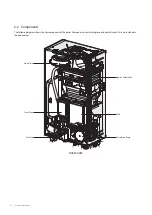
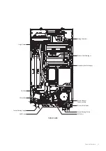
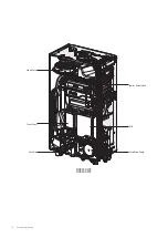
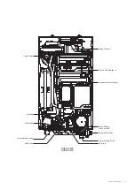
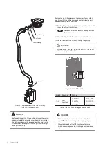
8. With the internal components exposed, locate the gas inlet
pipe and the gas valve in the middle of the unit, as shown in
Figure 2.
Gas Valve
Gas Inlet
Pipe
Figure 2. NCB300 Internal Components
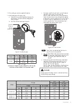
9. Loosen the hex nut at location A - the connection above
the gas valve where it connects to the pipe. See Figure 3 for
reference. Once the hex nut is loose, carefully separate the
pipe from the gas valve.
Procedure:
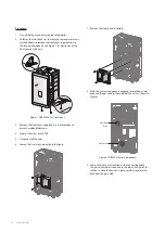
1. Turn off both gas and water supply to the boiler.
2. Unfasten the two latches (at the top) and remove two screws
(at the bottom) to remove the front cover to gain access to
the internal components. See Figure 1 for illustration of the
front cover on the unit.
Figure 1. NCB300 Series Front cover
3. Remove the front cover and place it in a safe location to
prevent accidental damage.
4. Label all the wires on the PCB.
5. Disconnect all the wires.
6. Loosen the five screws indicated in the figure.
Summary of Contents for NCB300-28K
Page 3: ......
Page 4: ...Revisions 3 Version Description of changes Date 1 00 First issue September 7 2022 Revisions...
Page 106: ...Memo...
Page 107: ...Memo...
Page 108: ...Memo...

