GV60 TROUBLESHOOTING MANUAL
RESPONDING TO ALARMS
VERSION 1.0 2018-01-01
PAGE 4.1.25
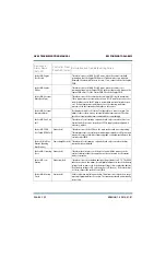
Exciter A/B: Reboot
For Settings Needed
(Need Reboot)
Exciter (red)
This alarm indicates that exciter setup changes have been made, typically
via the AUI. Typically, the DSP will reboot itself automatically. If the alarm
persists for more than five minutes, cycle the ac power (turn off, then on) to
store the changes.
Exciter A/B: Reduced
IBOC Injection
Exciter (red)
This alarm occurs if the HD optimizer has decreased the transmitter’s HD
injection level to ensure the output spectrum passes the mask. Typically
caused by a degrading output load impedance or PA or PS failures.
Exciter A/B: SCA 1 (or
2) Audio Low (SCA 1
or 2 Aud Low)
Exciter (amber)
This alarm indicates the SCA 1 or 2 input level is too low or is not applied.
The threshold and timing for this alarm can be adjusted in the Audio Low
menu in the user interface (see
) of the Operations & Maintenance Manual.
Exciter A/B: SRC1 (or
SRC2) Unlock
Exciter (amber)
This alarm indicates that no valid AES/EBU stream data is being detected on
the selected AES/EBU input. Check audio input cables. The GV60 takes no
action on this alarm.
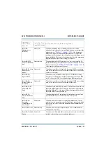
Exciter A/B: Summary
Alarm
-
Not displayed in AUI or UI status. Configurable as a remote output. This
alarms occurs if there are any alarms present. Check for specific alarms and
troubleshoot accordingly.
Exciter A/B: SWR
Foldback
Exciter (amber)
This alarm occurs if the exciter reduces its output power due to a high SWR.
The exciter will attempt to maintain a maximum reflected power level of
25 W at all times. Check the connection and the RF load at the exciter’s
output.
Exciter A/B: SWR
Shutback
Exciter (red)
This alarm occurs if there is a sudden increase in the reflected power sensed
by the exciter due to an external condition (e.g., open or shorted RF drive
cable). The exciter’s RF output is reduced to 0 W. The threshold for this
alarm is typically set to 75 W. Check the connection and the RF load at the
exciter’s output.
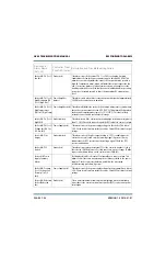
Exciter A/B:
Temperature
Summary Alarm
-
Not displayed in AUI or UI status. Configurable as a remote output. This
alarms occurs if there are high temperature related alarms occurring. Check
for specific temperature related alarms and troubleshoot accordingly.
Exciter A/B: Unsigned
DSP Image (Bad DSP
Image)
Exciter (red)
This alarm indicates that the exciter is operating with ‘unsigned code’, but
is otherwise operational. This alarm may only be displayed if the transmitter
is operating with a ‘beta’ version of factory software.
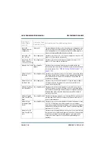
Exciter A/B: Unsigned
FPGA Image (Bad
FPGA Image)
Exciter (red)
This alarm indicates that the exciter is operating with ‘unsigned code’, but
is otherwise operational. This alarm may only be displayed if the transmitter
is operating with a ‘beta’ version of factory software.
Device and
Alarm Name
(AUI, UI)
Controller Front
Panel LED (color)
Description and Troubleshooting Action
Summary of Contents for GV60
Page 2: ......
Page 4: ......
Page 8: ...GV60 TROUBLESHOOTING MANUAL PAGE 4 VIII VERSION 1 0 2018 01 01 ...
Page 102: ...GV60 TROUBLESHOOTING MANUAL PARTS LISTS PAGE 4 2 12 VERSION 1 0 2018 01 01 ...
Page 463: ...VERSION 1 0 2018 01 01 MD 17 Figure MD 17 NAPA31C Power Amplifier PWB Q1 ...
Page 475: ...GV60 TROUBLESHOOTING MANUAL LIST OF TERMS PAGE 4 6 2 VERSION 1 0 2018 01 01 ...
Page 476: ......


