GV60 TROUBLESHOOTING MANUAL
RESPONDING TO ALARMS
PAGE 4.1.24
VERSION 1.0 2018-01-01
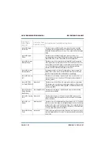
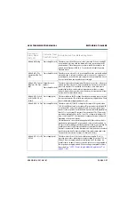
Exciter A/B: PA 1(or 2)
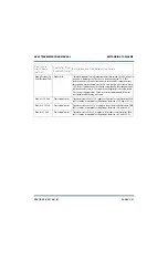
Fan Fail
Exciter (red)
This alarm occurs if the exciter's PA 1 (or PA 2) cooling fan has been
enabled, but the fan tachometer measurement is below 2000 RPM. This
alarm does not directly inhibit the exciter’s RF output, but may result in a
High PA Temperature alarm, which will inhibit the output. Inspect the fan
and, if necessary, replace it. In dual exciter systems, a changeover to the
standby exciter will occur if the faulty exciter is inhibited and its operating
power level is limited enough to affect the transmitter RF output power
level.
Exciter A/B: PA 1(or 2)
High Dissipation (PA
1(or 2) High Diss)
Power Amplifier
(amber)
This alarm occurs when there is excessive power dissipation (approximately
300 W) in the exciter’s power amplifier.
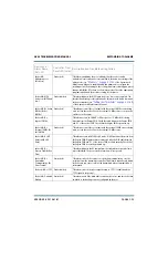
Exciter A/B: PA 1(or 2)
High Temperature
(PA1(or 2) High Temp)
Power Amplifier (red) This alarm will inhibit the exciter if the heatsink temperature sensed within
the exciter’s power stage exceeds 85°C (185°F). This alarm will clear when
the heatsink temperature decreases to 75°C (167°F). This fault is likely
related to an associated fan failure or blockage
.
Exciter A/B: PA 1(or 2)
High SWR
Exciter (amber)
This alarm occurs if the exciter is experiencing high reflected power (greater
than 17.5 W). Check the connection and the RF load at the exciter’s output.
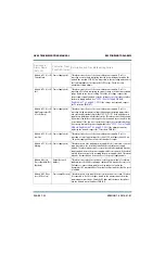
Exciter A/B: PA 1(or 2)
Voltage Fail (PA 1(or
2) Volts Fail)
Power Supply (red)
This alarm occurs if the power supply voltage for the exciter PA is below
20 V. Check for a blown fuse inside the exciter. Check LVPS module’s output
voltage.
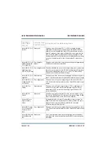
Exciter A/B: Pilot
Unsync
Exciter (amber)
This alarm occurs if the pilot output locking to 1 PPS is enabled, but the
exciter has not yet locked onto the incoming signal (if present). It may
indicate that the GPS receiver is not detecting a signal. Check the GPS
receiver and antenna.
Exciter A/B: PLL
Unlock
Exciter (red)
This alarm occurs when the internal PLL of the exciter in unable to lock to
the selected 10 MHz reference. Possible causes are an out-of-range 10 MHz
input or a hardware failure on the exciter/control PWB (A1).
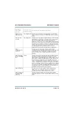
Exciter A/B: Power
Supply Summary
Alarm
-
Not displayed in AUI or UI status. Configurable as a remote output. This
alarm occurs if there are any alarms present that are related to the power
supplies. Check for associated alarms, and follow the associated
troubleshooting procedure, if present.
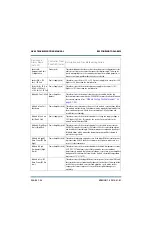
Exciter A/B: Preamp
1(or 2) Voltage Fail
(Preamp 1(or 2) V
Fail)
Power Supply (red)
This alarm occurs if the power supply voltage for the pre-amplifier is below
20 V. Check for a blown fuse inside the exciter. Check LVPS module’s output
voltage.
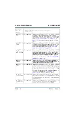
Exciter A/B: Rebooted
Exciter (Rebooted
Exc)
Exciter (red)
This is an informational alarm only that is displayed when the watchdog
timer reboots the exciter’s main microcontroller (DSP) or after an ac power
interruption.
Device and
Alarm Name
(AUI, UI)
Controller Front
Panel LED (color)
Description and Troubleshooting Action
Summary of Contents for GV60
Page 2: ......
Page 4: ......
Page 8: ...GV60 TROUBLESHOOTING MANUAL PAGE 4 VIII VERSION 1 0 2018 01 01 ...
Page 102: ...GV60 TROUBLESHOOTING MANUAL PARTS LISTS PAGE 4 2 12 VERSION 1 0 2018 01 01 ...
Page 463: ...VERSION 1 0 2018 01 01 MD 17 Figure MD 17 NAPA31C Power Amplifier PWB Q1 ...
Page 475: ...GV60 TROUBLESHOOTING MANUAL LIST OF TERMS PAGE 4 6 2 VERSION 1 0 2018 01 01 ...
Page 476: ......


