GV60 TROUBLESHOOTING MANUAL
RESPONDING TO ALARMS
VERSION 1.0 2018-01-01
PAGE 4.1.17
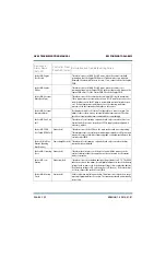
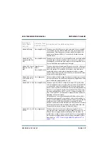
Controller: Rack
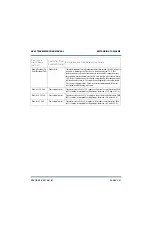
Shutback
Power Amplifier (red) This alarm indicates a connection issue between the controller and the
(rack) module control/interface PWB(s), such that the “shutback” signal is
unavailable due to a hardware fault (typically, the 9-pin D-sub daisy-chain
cable is disconnected). In addition, a “Rack # Offline” alarm will also be
present to signify a communication loss between the controller and (rack)
module control/interface PWB(s).
Controller: Rack 1-6
Sync Required
Power Amplifier (red) This alarm indicates that the Rack data for scale factors or transmitter type
is out of sync with the Controller data. This condition is automatically
resolved based on the controller's internal rules for transmitter type
determination. This alarm will appear in the events log only, and the
customer does not need to take any action.
Controller: Rebooted
Exciter
Exciter (red)
This is an informational alarm only that is displayed when the watchdog
timer reboots the controller’s main microcontroller (DSP) or on an ac power
interruption.
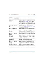
Controller: Reboot
Required (Need
Reboot for Settings)
Exciter (red)
This alarm indicates that exciter setup changes have been made, typically
via the System Settings page of the AUI. Typically, the DSP will reboot itself
automatically; however, if this alarm persists for more than five minutes,
cycle the transmitter’s ac power (off, then on) to store the changes.
Controller: Reduced
Power Summary
Output Network
(amber)
Not displayed in AUI or UI status. Configurable as a remote output. This
alarms occurs if there are any alarms present that caused the transmitter’s
RF output power to be reduced. Check for associated alarms, and follow the
associated troubleshooting procedure, if present.
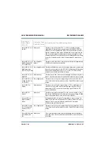
Controller: Reject
Foldback (Rej
Foldback)
Output Network
(amber)
This alarm occurs if any of the transmitter’s reject load
’
s’ average power
exceeds its reject power foldback threshold (1500 W). The transmitter’s
forward power will be reduced each time the alarm occurs, until the fault
clears. Typically, high reject power is a result of RF power module failure or
removal, or PA power supply failure or removal. Check for associated
alarms, and follow the associated troubleshooting procedure if present.
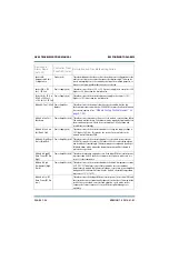
Controller: Reject
Shutback
Output Network (red) This alarm occurs if any of the transmitter’s reject load
’
s’ average power
exceeds its reject power shutback threshold (1800 W). The transmitter will
be shut back and attempt to find a safe operating power level by entering
reject foldback mode. Typically, high reject power is a result of RF power
module failure or removal, or PA power supply failure or removal. Check for
associated alarms, and follow the associated troubleshooting procedure if
present.
Device and
Alarm Name
(AUI, UI)
Controller Front
Panel LED (color)
Description and Troubleshooting Action
Summary of Contents for GV60
Page 2: ......
Page 4: ......
Page 8: ...GV60 TROUBLESHOOTING MANUAL PAGE 4 VIII VERSION 1 0 2018 01 01 ...
Page 102: ...GV60 TROUBLESHOOTING MANUAL PARTS LISTS PAGE 4 2 12 VERSION 1 0 2018 01 01 ...
Page 463: ...VERSION 1 0 2018 01 01 MD 17 Figure MD 17 NAPA31C Power Amplifier PWB Q1 ...
Page 475: ...GV60 TROUBLESHOOTING MANUAL LIST OF TERMS PAGE 4 6 2 VERSION 1 0 2018 01 01 ...
Page 476: ......


