GV60 TROUBLESHOOTING MANUAL
RESPONDING TO ALARMS
PAGE 4.1.20
VERSION 1.0 2018-01-01
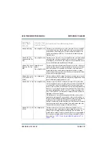
Controller: 10kW
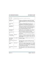
Reject Fan 1 - 6 Fail
(10kW Rej Fan1-3
Fail)
Output Network
(red)
This alarm occurs if the 10 kW reject load (A31or A131) cooling fans are
enabled and the speed of a cooling fan [B4 (1), B5 (2) or B6 (3)for cabinet A;
B104 (4), B105 (5) or B106 (6) for cabinet B] is below 2000 RPM. 10 kW
reject load cooling fans are enabled only when the reject load power is
greater than 300 W, possibly due to an RF power module removal or failure
or power supply removal or failure. Inspect the fan and, if necessary, replace
it (see
“Cooling Fan Replacement” on page 4.1.56
Controller: +12V A
Fail
Power Supply (red)
This alarm occurs if the +12 V supply in the controller is 10% lower or 10%
higher than the desired value. Check the output voltage of the LVPS module.
If necessary, replace the LVPS (see
). There may also be a problem with the
controller’s power supply PWB.
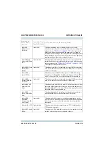
Controller: +12V B
Fail
Power Supply (red)
This alarm occurs if the sec12 V supply in the controller is 10%
lower or 10% higher than the desired value. Check the output voltage of
the LVPS module. If necessary, replace the LVPS (see
Supply Module Replacement” on page 4.1.50
). There may also be a
problem with the controller’s power supply PWB.
Controller: +15V Fail
Power Supply (red)
This alarm occurs if the +15 V power supply in the controller is 2 V higher or
2 V lower than the desired value. There may also be a problem with the
controller’s power supply PWB.
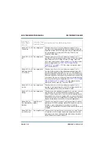
Controller: -15V Fail
Power Supply (red)
This alarm occurs if the -15 V power supply in the controller is 2 V higher or
2 V lower than the desired value. There may also be a problem with the
controller’s power supply PWB.
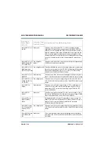
Controller: 5kW
Reject Fan 1 - 10 Fail
(5kW Rej Fan1-6 Fail)
Output Network
(red)
This alarm occurs if the 5 kW reject load (A27 or A29 for cabinet A; A127 or
A129 for cabinet B) cooling fans are enabled and the speed of a cooling fan
[B8 (1), B9 (2), B10 (3), B11 (4) or B12 (5) for cabinet A; B108 (6), B109 (7),
B110 (8), B111 (9) or B112 (10) for cabinet B] is below 2000 RPM. 5 kW
reject load cooling fans are enabled only when the reject load power is
greater than 300 W, possibly due to an RF power module removal or failure.
Inspect the fan and, if necessary, replace it (see
).
Controller: +5V A Fail Power Supply (red)
This alarm occurs if the +5 V supply in the controller is 10% lower or 10%
higher than the desired value. Check the output voltage of the LVPS module.
If necessary, replace the LVPS (see
). There may also be a problem with the
controller’s power supply PWB.
Device and
Alarm Name
(AUI, UI)
Controller Front
Panel LED (color)
Description and Troubleshooting Action
Summary of Contents for GV60
Page 2: ......
Page 4: ......
Page 8: ...GV60 TROUBLESHOOTING MANUAL PAGE 4 VIII VERSION 1 0 2018 01 01 ...
Page 102: ...GV60 TROUBLESHOOTING MANUAL PARTS LISTS PAGE 4 2 12 VERSION 1 0 2018 01 01 ...
Page 463: ...VERSION 1 0 2018 01 01 MD 17 Figure MD 17 NAPA31C Power Amplifier PWB Q1 ...
Page 475: ...GV60 TROUBLESHOOTING MANUAL LIST OF TERMS PAGE 4 6 2 VERSION 1 0 2018 01 01 ...
Page 476: ......


