


© National Instruments
|
8-25
NI High-Speed Serial Instruments User Manual
To reserve multiple trigger lines, repeat steps 2 to 6 for each trigger line you want to reserve,
wiring the
FPGA VI Reference Out
output of the existing Invoke Method function to the
FPGA VI Reference In
input of the Invoke Method node that follows it.
Releasing Trigger Lines
Complete the following steps to release a trigger line for your device.
Note
LabVIEW automatically releases the trigger reservation when you close the
FPGA VI Reference, but you can use an invoke node if you want to unreserve the
trigger without closing the FPGA VI Reference.
1.
Place the Open FPGA VI Reference function on the block diagram and configure it for the
FPGA device and FPGA VI.
2.
Place the Invoke Method function on the block diagram.
3.
Wire the
FPGA VI Reference Out
output of the Open FPGA VI Reference function to
the
FPGA VI Reference In
input of the Invoke Method function.
4.
Wire the
error out
output of the FPGA VI Reference function to the
error in
input of the
Invoke Method function.
5.
Click the Invoke Method function and select
Unreserve PXI Trigger
from the
shortcut menu.
6.
Right-click the
Trigger
input and select
Create»Constant
. An enum constant is created
to help you select the trigger.
To release multiple trigger lines, repeat steps 2 to 6 for each trigger line you want to release,
wiring the
FPGA VI Reference Out
output of the existing Invoke Method function to the
FPGA VI Reference In
input of the Invoke Method node that follows it.
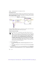
Monitoring Power and Temperature
Due to the degree of customization possible with the high-speed serial device FPGAs, some
applications may draw too much power or dissipate too much heat. Monitor the device state
carefully, especially if your device pushes the power or heat limits. Use the Read Module
Temperature and Read Module Power method nodes to monitor device temperature and heat,
respectively.
Read Module Temperature allows you to read two onboard sensors: one sensor is embedded
directly in the FPGA, and one reads the device temperature.
Figure 8-8.
Read Module Temperature
Artisan Technology Group - Quality Instrumentation ... Guaranteed | (888) 88-SOURCE | www.artisantg.com


