


© National Instruments
|
8-15
NI High-Speed Serial Instruments User Manual
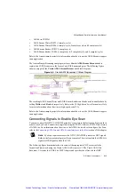
The following steps show an example of how to configure the PXIe-6592R for 140 MHz output
on MGT_RefClk0 from a 100 MHz input clock on PFI0/CLK IN.
1.
Right-click the IO socket and select
Properties»Clocking and IO
.
2.
Under
Input Clock Configuration
, select
PFI0/CLK IN
and enter
100
.
3.
Under
Output Clock Configuration
, select the checkbox next to
MGT_RefClk0
to
enable it.
4.
Enter
140
in the text box to the right of
MGT_RefClk0
.
5.
Click
OK
.
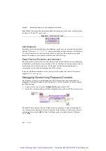
Note
By selecting an input clock and an output clock in this example, the
MGT_RefClk0 is phase loop-locked to the incoming 100 MHz clock.
Refer to Chapter 2,
PXIe-6591R Hardware Architecture
, for more information about PXIe-6591R
clocking capabilities.
Refer to Chapter 4,
PXIe-6592R Hardware Architecture
, for more information about
PXIe-6592R clocking capabilities.
Refer to Chapter 6,
PXIe-7902 Hardware Architecture
, for more information about PXIe-7902
clocking capabilities.
Using Existing VHDL IP inside CLIP or IPIN
To use existing IP in your project, refer to the
Importing External IP Into LabVIEW FPGA
white
paper at
ni.com
.
CLIP does not support custom user libraries in the VHDL. If your VHDL uses custom user
libraries, use one of the following workarounds:
•
Create a netlist from the VHDL and integrate the netlist using CLIP.
•
Reference the default reference library instead of a custom user library.
Refer to the
Creating or Acquiring IP (FPGA Module)
topic in the
LabVIEW FPGA Module
Help
for more information about using existing VHDL IP inside CLIP or IPIN.
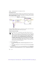
Adding High-Speed Serial Device Target I/O
Complete the following steps to add target I/O for the high-speed serial device and to access
signals from any instantiated CLIP on the block diagram:
1.
Place an FPGA I/O node on the FPGA target block diagram. The FPGA I/O node is located
on the palette under
Functions»FPGA I/O»FPGA I/O Node
.
2.
Right-click the FPGA I/O node and select
Add New FPGA I/O
.
3.
In the
New FPGA I/O
dialog box, select resources under
Available Resources
and add
them to
New FPGA I/O
using the right arrow button.
Artisan Technology Group - Quality Instrumentation ... Guaranteed | (888) 88-SOURCE | www.artisantg.com


