background image

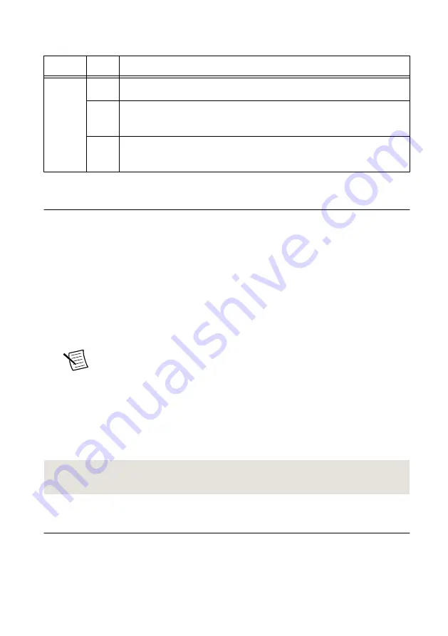
Table 3. Front Panel LEDs (Continued)

LED

State

Indications


ACTIVE Off

The module is not generating a signal.

Green The module is generating a signal; applicable phase-locked loops (PLLs)

are locked.

Red

The module has detected an error state; this may indicate a PLL lock
failure or a thermal shutdown condition.

Configuring the PXIe-5654 in MAX

Use Measurement & Automation Explorer (MAX) to configure your NI hardware. MAX
informs other programs about which NI hardware products are in the system and how they are
configured. MAX is automatically installed with NI-RFSG.
1.

Launch MAX.

2.

In the configuration tree, expand 

Devices and Interfaces

 to see the list of installed NI

hardware.

Installed modules appear under the name of their associated chassis.

3.

Expand your 

Chassis

 tree item.

MAX lists all modules installed in the chassis. Your default names may vary.

Note


If you do not see your module listed, press <F5> to refresh the list of

installed modules. If the module is still not listed, power off the system, ensure
the module is correctly installed, and restart.

4.

Record the identifier MAX assigns to the hardware. Use this identifier when
programming the PXIe-5654.

5.

Self-test the hardware by selecting the item in the configuration tree and clicking 

Self-

Test

 in the MAX toolbar.

The MAX self-test performs a basic verification of hardware resources.

Related Information

Refer to the NI RF Signal Generators Help for information about renaming devices.

Programming the PXIe-5654

You can generate signals interactively using the NI-RFSG Soft Front Panel (SFP), or you can
use the NI-RFSG instrument driver to program your device in the supported ADE of your
choice.

10

  | 

ni.com

  | 

PXIe-5654 Getting Started Guide

Summary of Contents for PXIe-5654

Page 1: ...ons et respectez toutes les mises en garde de la documentation d utilisation L utilisation du produit de toute autre fa on que celle sp cifi e risque de l endommager et de compromettre la protection d...

Page 2: ...nuals for more information about minimum system requirements recommended system and supported application development environments ADEs Unpacking the Kit Notice To prevent electrostatic discharge ESD...

Page 3: ...ce kit that you need to install or operate the PXIe 5654 Required Items A PXI Express chassis and chassis documentation The PXIe 1085 chassis is one available option for your device For more informati...

Page 4: ...about installing removing and upgrading NI software using NI Package Manager 3 Follow the instructions in the installation prompts to install the NI RFSG driver software Note Windows users may see acc...

Page 5: ...Chassis Compatibility Symbols 1 2 3 4 5 1 PXI Express System Controller Slot 2 PXI Peripheral Slot 3 PXI Express Hybrid Peripheral Slot 4 PXI Express System Timing Slot 5 PXI Express Peripheral Slot P...

Page 6: ...els depending on your application Note For more information about installing slot blockers and filler panels go to ni com r pxiblocker 12 Power on the chassis Related Information Installing the Softwa...

Page 7: ...ded to complete the tightening of the SMA cable to 1 N m Rotate the torque wrench no more than one revolution to tighten the SMA cable before reaching maximum torque Related Information Refer to the P...

Page 8: ...2 dBm NOM REF OUT 2 100 MHz 5 dBm 2 dBm NOM TRIG IN OUT 3 3V CMOS IN OUT 0 5V MIN IN 5 5V MAX IN ESD SENSITIVE ALL PORTS 50 Table 1 Device Front Panel Icon Definitions Refer to the user documentation...

Page 9: ...at accepts a modulating square wave to pulse the RF output FM IN Input terminal for frequency modulation AM IN Input terminal for amplitude modulation ALC IN Input terminal that connects to the ALC OU...

Page 10: ...pand your Chassis tree item MAX lists all modules installed in the chassis Your default names may vary Note If you do not see your module listed press F5 to refresh the list of installed modules If th...

Page 11: ...ation in Microsoft Visual C C Related Information Refer to the Getting Started topic of the NI RF Signal Generators Help for instructions about how to generate signals in a specific ADE Refer to the C...

Page 12: ...NI RFSG SFP generates an error During signal generation the ACTIVE LED on the PXIe 5654 hardware module illuminates 5 Click RF On Off to stop signal generation Building a Basic NI RFSG Application Yo...

Page 13: ...he VI front panel power level dBm control enter 0 In the frequency Hz control enter 100M 100 MHz 12 In the VI front panel resource name control enter the PXIe 5654 device name that you specified in MA...

Page 14: ...output of the status element to an input of the Or function 9 Right click the unused input of the Or function and select Create Control to create a Boolean control 10 In the VI front panel right clic...

Page 15: ...specified in MAX in the resource name control 4 Click the Run button on the toolbar to initiate sine wave generation 5 Click the VI front panel STOP button to stop sine wave generation You have succes...

Page 16: ...it for damage Do not reinstall a damaged device 4 Reinstall the module in a different chassis slot 5 Power on the chassis 6 Verify that the device appears in MAX 7 Reset the device in MAX and perform...

Page 17: ...downloads and troubleshooting and application development self help such as tutorials and examples Visit ni com services to learn about NI service offerings such as calibration options repair and rep...

Page 18: ...LAs and third party legal notices in the readme file for your NI product Refer to the Export Compliance Information at ni com legal export compliance for the NI global trade compliance policy and how...

Reviews: