PXIe-5654 RF Signal Generator Module
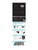
The PXIe-5654 RF signal generator contains nine connectors and two multicolor LEDs.
Figure 4. PXIe-5654 RF Signal Generator Module Front Panel
250 kHz–20 GHz Signal Generator
ACCESS
ACTIVE
REF IN
1–20 MHz
±10 dBm NOM
17 dBm MAX
PULSE
IN
–0.5V MIN
+5.5V MAX
FM IN
±1 VDC NOM
±2 VDC MAX
AM IN
±1 VDC NOM
±2 VDC MAX
ALC IN
±15 VDC MAX
RF OUT
250 kHz –
20 GHz
REF OUT
10 MHz
5 dBm ±2 dBm NOM
REF OUT 2
100 MHz
5 dBm ±2 dBm NOM
TRIG
IN/OUT
3.3V CMOS
IN/OUT
–0.5V MIN IN
5.5V MAX IN
ESD
SENSITIVE
ALL PORTS
50
Ω
Table 1. Device Front Panel Icon Definitions
Refer to the user documentation for required maintenance measures to ensure user
safety and/or preserve the specified EMC performance.
The signal pins of this product's input/output ports can be damaged if subjected to
ESD. To prevent damage, turn off power to the product before connecting cables and
employ industry-standard ESD prevention measures during installation, maintenance,
and operation.
8
|
ni.com
|
PXIe-5654 Getting Started Guide