©
National Instruments Corporation
17
NI 5622 Calibration Procedure
8.
This step varies depending on the programming language used.
(LabVIEW)
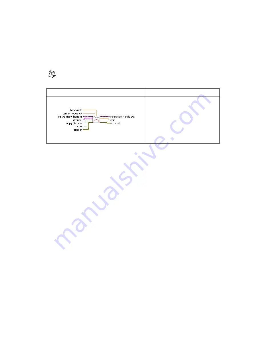
Configure the frequency response compensation using the Apply
Frequency Response Compensation VI. The value returned is the
Reference Flatness Gain Correction Factor
used in step 15.
Note
You can download the Apply Frequency Response Compensation VI from the
NI Web site at
ni.com/info
. Use the Info Code
ex6vhg
.
(C/C++)
Configure the custom coefficients for the equalization FIR filter of
the digitizer. Use the following function and attribute calls
to calculate the customer coefficients.
a.
To get the frequency response of the digitizer, call
niScope_GetFrequencyResponse
.
b.
To get the number of coefficients the FIR filter can accept, call the
NISCOPE_ATTR_EQUALIZATION_NUM_COEFFICIENTS
attribute.
c.
To configure the custom coefficients for the FIR filter, call
niScope_ConfigureEqualizationFilterCoefficients
.
9.
Configure the signal generator to generate an
Input Frequency, Input
Voltage
sine wave for the current iteration in Table 4.
10. Wait the amount of time the manufacturer recommends for the output
to settle.
11. Measure the power (in watts) of the sine wave using the power meter.
This value is the
Power Meter Measured Sine Wave Power
used in
LabVIEW VI
Input Parameters
Set the following parameters:
bandwidth
:
–1
center frequency
: The
Reference
Frequency
value in Table 4 for the
current iteration
channel
:
“0”
apply flatness
:
TRUE
cache
:
FALSE


