2-
8
|
ni.com
Chapter 2
Using the NI PXIe-4300
–
Continuous acquisition refers to the acquisition of an unspecified number of samples.
Instead of acquiring a set number of data samples and stopping, a continuous
acquisition continues until you stop the operation. Continuous acquisition is also
referred to as double-buffered or circular-buffered acquisition.
If data cannot be transferred across the bus fast enough, the FIFO becomes full. New
acquisitions overwrite data in the FIFO before it can be transferred to host memory.
The device generates an error in this case. With continuous operations, if the
application program does not read data out of the PC buffer fast enough to keep up
with the data transfer, the buffer could reach an overflow condition, causing an error
to be generated.
•
Hardware-timed single point (HWTSP)—Typically, HWTSP operations are used to read
single samples at known time intervals. While buffered operations are optimized for high
throughput, HWTSP operations are optimized for low latency and low jitter. In addition,
HWTSP can notify software if it falls behind hardware. These features make HWTSP ideal
for real-time control applications. HWTSP operations, in conjunction with the wait for next
sample clock function, provide tight synchronization between the software layer and the
hardware layer. Refer to the whitepaper
NI-DAQmx Hardware-Timed Single Point
Lateness Checking
for more information. To access this document, go to
and enter the Info Code
daqhwtsp
.
Analog Input Filter
The NI PXIe-4300 has selectable filter settings per channel. Each channel can independently be
set to one of the three available lowpass filter settings: 10 kHz, 100 kHz, and Disable. The
10 kHz and 100 kHz filters are 2-pole Butterworth filters, and their designation refers to the
-3 dB cut-off frequency. The
Disable
setting bypasses the filters and allows measurements in the
full bandwidth of the NI PXIe-4300.
Gain
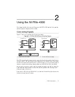
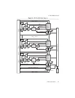
The NI PXIe-4300 module implements the different analog input COM-reference settings by
routing different signals to the PGIA. The PGIA is a differential amplifier so it amplifies (or
attenuates) the difference in voltage between its two inputs. The PGIA drives the ADC with this
amplified voltage. The amount of amplification (the gain), is determined by the analog input
range, as shown in Figure 2-3.
Note
Time and temperature can introduce gain and offset AI errors at runtime. You
can minimize these errors by self-calibrating the module.


