© National Instruments
|
2-1
2
Using the NI PXIe-4300
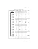
This chapter describes how to connect AI inputs to the NI PXIe-4300 module. It also provides
the front signal pin assignments of the module.
Connecting Signals
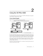
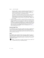
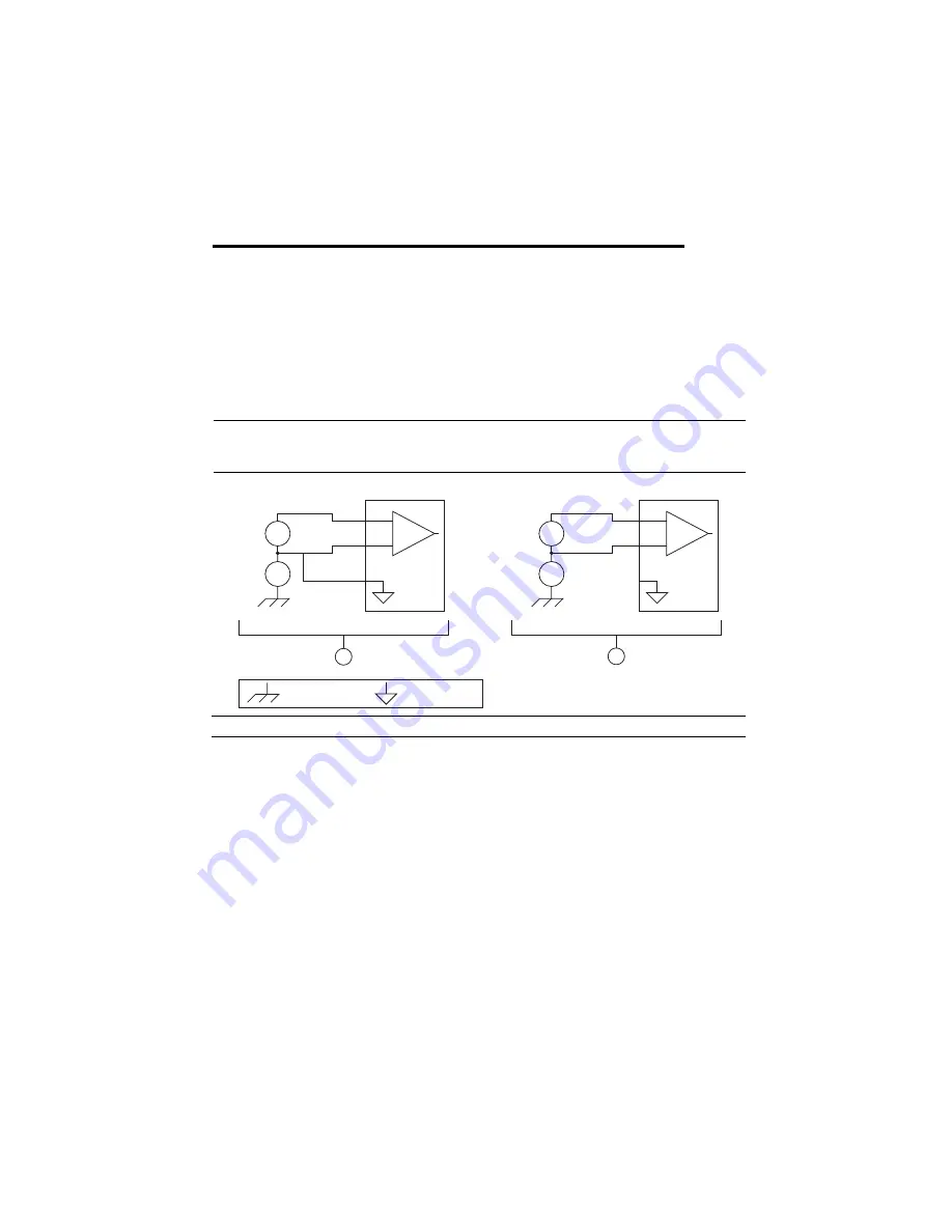
Figure 2-1 shows correct and incorrect AI source grounding.
Figure 2-1.
NI PXIe-4300 AI Source Grounding Diagram
The COM terminal for each channel must be connected to the reference ground of the AI source.
Failure to connect COM results in inaccurate measurements. You can connect the COM terminal
directly to the negative terminal of the source as shown in Figure 2-1 or to an isolated ground of
the source as long as the working voltage specification of the NI PXIe-4300 is not violated.
For best results, wire the AI+ and AI- signals as twisted pairs and use the COM as a shield. The
COM connection should be made as close to the source as possible to take advantage of the
differential nature of this device.
Refer to the
NI PXIe-4300 and TB-4300/B/C User Guide and Terminal Block Specifications
for
details about signal terminal locations.
1
Correct AI Source Grounding
2
Incorrect AI Source Grounding
+
–
+
–
AI+
AI–
COM
S
ign
a
l
S
o
u
rce
AI Ch
a
nnel
+
–
+
–
AI+
AI–
COM
S
ign
a
l
S
o
u
rce
AI Ch
a
nnel
2
1
+
–
+
–
V
S
IG
V
CM
V
S
IG
V
CM
I
s
ol
a
ted Gro
u
nd
Ch
ass
i
s
Gro
u
nd


