background image

USER GUIDE

FD-11613

8-Channel Temperature Input Device for FieldDAQ

The FieldDAQ FD-11613 is an IP65/IP67-rated eight-channel thermocouple device that can be
networked and synchronized with IEEE 802.1AS devices. The FD-11613 supports B, E, J, K,
N, R, S, and T thermocouple types.

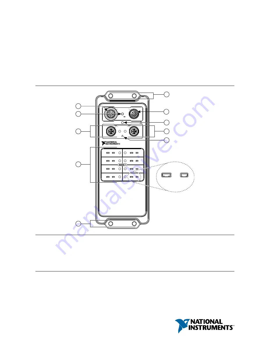
Figure 1. FD-11613 Front Panel

0

10/100/1000

LINK/ACT

FD-11613

24-Bit Thermocouple Input

SYNC

1

IN

10 A  TOTAL

9-30 V

FieldDAQ

STATUS

OUT

0

2

4

6

1

3

5

7

2

6

7

1

8

3

5

5

4

TC–

TC+

9

1. Power IN Connector
2. Power LED
3. Ethernet Port 0 and LED
4. Thermocouple Connectors and Open

Thermocouple LEDs

5. Mounting Holes

6. Power OUT Connector
7. STATUS LED
8. Ethernet Port 1 and LED
9. SYNC Logo

Summary of Contents for FD-11613

Page 1: ...pports B E J K N R S and T thermocouple types Figure 1 FD 11613 Front Panel 0 10 100 1000 LINK ACT FD 11613 24 Bit Thermocouple Input SYNC 1 IN 10 A TOTAL 9 30 V FieldDAQ STATUS OUT 0 2 4 6 1 3 5 7 2...

Page 2: ...e Based Triggers 18 Timebases 19 Synchronization across a Network 20 More Information about Synchronization 20 Ethernet Ports and Networking 20 Ethernet Ports 20 Ethernet LEDs 21 Internal Ethernet Swi...

Page 3: ...n page 12 Driver Support Earliest driver support version for your FieldDAQ device Table 1 FD 11613 Driver Support Driver Earliest Version Support NI DAQmx 17 6 Cables and Accessories The following tab...

Page 4: ...s user guide Product misuse can result in a hazard You can compromise the safety protection built into the product if the product is damaged in any way If the product is damaged return it to National...

Page 5: ...product visit ni com certification and search for the certificate Notice In order to meet the EMC requirements for marine applications install the product in a shielded enclosure with shielded and or...

Page 6: ...liance go to ni com environment rohs_china What You Need to Get Started You will need the following items to set up your FieldDAQ device Figure 2 FieldDAQ Installation Supply List 2 1 7 3 NI DAQmx 4 8...

Page 7: ...e input Refer to Thermocouple Connectors for information about thermocouple signal connections and guidelines 6 Carefully align and connect one end of the Ethernet cable to Ethernet port 0 on the devi...

Page 8: ...click the FieldDAQ device and select Add Device If the device is not on your local subnet right click Network Devices and select Find Network NI DAQmx Devices 9 In the Find Network NI DAQmx Devices di...

Page 9: ...d of the Find Network NI DAQmx Devices window and click the button Enter the hostname of the device The default hostname is FD11613 serial number 10 Click Add Selected Devices The FieldDAQ device icon...

Page 10: ...11 If the FieldDAQ device is not reserved automatically select the device and click the Reserve Network Device button Refer to Reserving the Device in MAX for more information 12 Self test your devic...

Page 11: ...D 11613 Specifications Recommended NI power supplies are listed in FD 11613 Basic Information The FD 11613 has a maximum device power consumption of 4 9 W Each FieldDAQ filters and regulates the suppl...

Page 12: ...age line 2 Aux2 Optional line for powering non FieldDAQ devices 3 C Common Negative voltage line 4 Aux1 Optional line for powering non FieldDAQ devices 5 Chassis Ground Power LED The green POWER LED o...

Page 13: ...lly align and connect the cable to the external power source and the power IN connector on the FieldDAQ device 4 Turn on the external power source If the power source is connected to the power connect...

Page 14: ...ting from the source impedance of connected thermocouples are negligible for most applications Thermocouples with a higher lead resistance can introduce more significant errors Open Thermocouple Detec...

Page 15: ...ultaneously passes through a filtered differential amplifier before being sampled by a 24 bit ADC The FieldDAQ device provides overvoltage protection for each channel refer to the FD 11613 Specificati...

Page 16: ...sure that devices you connect to the FD 11613 are compatible with the device specifications Refer to your thermocouple documentation or the thermocouple wire spool to determine which wire is the posi...

Page 17: ...rminals Programming the FieldDAQ Device You can use the FieldDAQ device in the following analog input applications Single point acquisition Finite acquisition Continuous acquisition The FieldDAQ devic...

Page 18: ...e Clock Timebase signal is divided down to provide a source for Sample Clock AI Start Trigger Signal Use the Start Trigger signal to begin a measurement acquisition A measurement acquisition consists...

Page 19: ...Host Time to I O Device Time as necessary The accuracy of this translation depends on the relationship between these times and can reduce the relative accuracy of time triggers across multiple device...

Page 20: ...onsidering topologies masters and third party devices If topology changes result in a device s master changing executing tasks may be affected Visit ni com info and enter fdenet How to achieve high ac...

Page 21: ...the Ethernet ports to reset the FieldDAQ device to factory default settings Refer to Resetting the FieldDAQ to Factory Default Settings for more information Cap the Ethernet ports when not in use Eth...

Page 22: ...network to synchronize The IEEE 802 1AS protocol is an IEEE 1588 profile but is incompatible with other IEEE 1588 profiles These FieldDAQ devices cannot synchronize over the network with devices that...

Page 23: ...in a properly configured network For more information about the recommended configurations for networking the FieldDAQ device refer to Topology Options Topology Options Recommended networking topolog...

Page 24: ...or systems that require a greater number of nodes Note For information about daisy chaining power refer to Power Connectors and Wiring Ring Topology In a ring topology the host communicates with all n...

Page 25: ...must use an external switch in a star topology for network synchronization you must use an external 802 1AS switch Redundant links are recommended but optional in this topology You must configure the...

Page 26: ...synchronization and network redundancy features of the FieldDAQ device ensure that your network infrastructure meets certain requirements IEEE 802 1AS 2011 time based synchronization support Automatic...

Page 27: ...installation of the NI DAQmx feature to the controller In MAX expand Remote Systems your Real Time Controller and use the Add Remove Software option Select the custom installation option and the NI D...

Page 28: ...ct your system administrator to confirm that the network is working and that a firewall is not interfering with discovery For additional troubleshooting resources for the FieldDAQ device refer to Trou...

Page 29: ...device to a new network NI DAQmx may lose connection to the device In this case click Reconnect to provide NI DAQmx with the new hostname or IP address The FieldDAQ device icon indicates whether it i...

Page 30: ...te Device Status Off Device is reserved by NI DAQmx but there is no activity the device is not powered or the device is not reserved by NI DAQmx Yellow solid Device firmware is booting or updating Red...

Page 31: ...ngs Attribute Value Hostname FD11613 serial number IP DHCP or Link Local Comment Empty Default login User name admin Password no password required Mounting FieldDAQ can be mounted on any substrate in...

Page 32: ...in thick and extends a minimum of 76 2 mm 3 in beyond all edges of the device 3 Observe the cooling dimensions in Mounting Requirements 4 Allow space for cabling clearance according to the Mounting R...

Page 33: ...evice for air circulation as shown in the following figure Figure 22 Cooling Dimensions 76 2 mm 3 00 in All Around Cooling Dimensions STATUS IN 10 A TOTAL 9 30 V FieldDAQ OUT 0 10 100 1000 LINK ACT SY...

Page 34: ...vertical mounting configurations Figure 24 Ambient Temperature Locations Horizontal Mounting Configuration 25 4 mm 1 00 in 76 2 mm 3 00 in 25 4 mm 1 00 in 38 7 mm 1 50 in 76 2 mm 3 00 in 38 7 mm 1 50...

Page 35: ...For detailed dimensional drawings and 3D models visit ni com dimensions and search for FD 11613 Mounting the Device Directly on a Flat Surface For environments with high shock and vibration NI recomm...

Page 36: ...0 LINK ACT SYNC 1 2 Align the device on the surface 3 Fasten the device to the surface using the M5 or 10 32 screws Tighten the screws to a maximum torque of 2 5 N m 25 0 lb in Figure 27 Fastening the...

Page 37: ...ple programs for the FieldDAQ device and relevant documentation Example Programs NI DAQmx software includes example programs to help you get started programming with the FieldDAQ device Modify example...

Page 38: ...abVIEW Help available by selecting Help LabVIEW Help in LabVIEW to access information about LabVIEW programming concepts step by step instructions for using LabVIEW and reference information about Lab...

Page 39: ...eractively create channels and tasks using Measurement Studio and the DAQ Assistant Additionally you can use Measurement Studio to generate the configuration code based on your task or channel Refer t...

Page 40: ...information on NI trademarks Other product and company names mentioned herein are trademarks or trade names of their respective companies For patents covering NI products technology refer to the appr...

Reviews: