North American Clutch & Driveline
Rockford, Illinois
Phone: (800) 383-9204
(815) 282-7960
Fax (815) 282-9160
www.naclutch.com
48
12.3.2 Using the hoist, carefully lower the
shaft and bearing housing onto the bell
housing. Position the threaded hole in
the bearing housing flange (the hole is for
grease fitting (7) in line with the inspection
opening in the bell housing. (See illustration
in section 6.1.2.)
12.3.3 Install bolts and lockwashers (43
and 44). Torque to specifications:
Used without support plates (5/8” - 11
bolts)
Grade 5 117-140 ft. lbs. (159-190 Nm.)
Used with support plates (5/8” -11 bolts)
Grade 8 134-160 ft. lbs. (182-217 Nm.)
12.4 Install the cross shaft and clutch
release yoke.
12.4.1 Lubricate the cross shaft holes in
the bell housing. Slide the cross shaft (14)
through one hole.
12.4.2 Slide the clutch release yoke
(17) onto the cross shaft. The bolt holes
(unthreaded end) should face outward
(toward the flywheel). Slide the cross shaft
through the release yoke and into the other
cross shaft hole in the bell housing.
12.4.3 Rotate and position the cross shaft
so one keyway is exposed in the middle
of the release yoke. The other keyway will
be located outside the yoke. Install (2)
woodruff keys (15) in the cross shaft.
12.4.4 Slide the cross shaft and woodruff
keys into the keyways of the release yoke
until the keys are centered on the yoke.
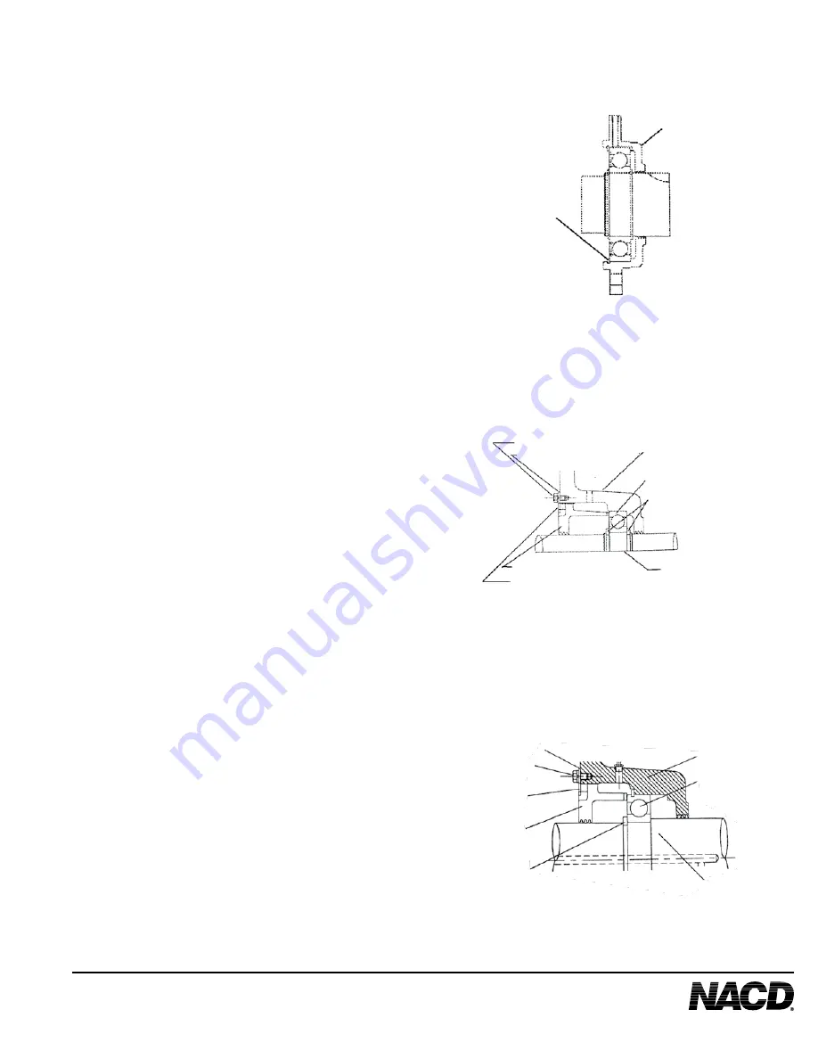
CONFIGURATION C
CONFIGURATION D
CONFIGURATION E
Bearing
Housing (30)
Internal
Snapring
(68)
Bell Housing (1)
Lock Bolt
(12)
Lockwasher (13)
Drive Shaft
(8)
Bearing Retainer
(10)
Adjustment Lock (11)
Main Bearing
(9)
External
Snaprings (29)
Lockwasher (13)
Lock Bolt
(12)
Adjustment
Lock (11)
Bearing
Retainer (10)
External Snaprings (29)
Bell Housing
(1)
Drive Shaft (8)
Main
Bearing
(9)


