EN
12
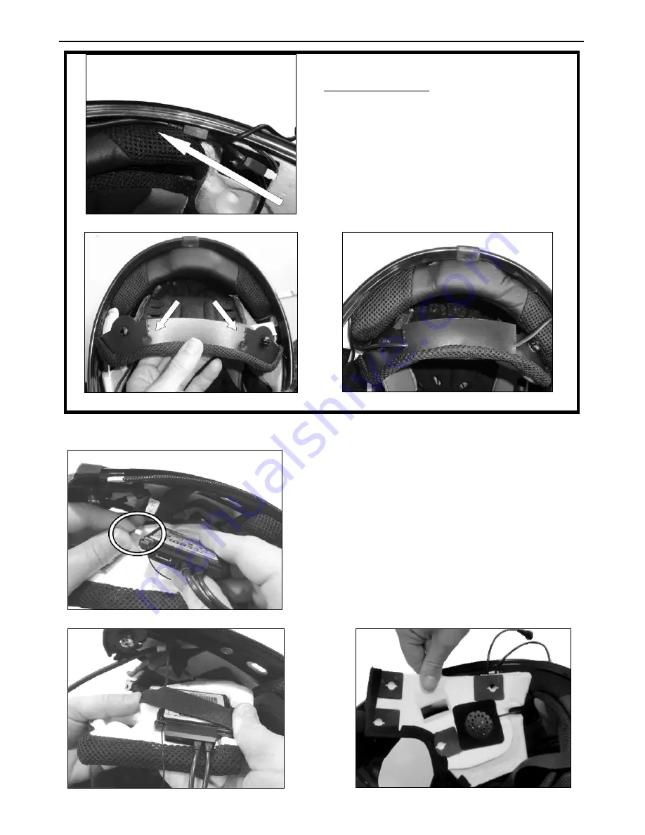
Fig. 21
Only for X702 helmet
Position the battery connector and wiring
underneath the shell gasket (Fig. 21).
Cut along the pre-cut lines of the plastic tab
on the back of the comfort padding (Fig. 22).
Secure the wiring underneath the plastic tab.
Close the cut parts using the cable fixing
adhesives (Fig. 23).
Fig. 22
Fig. 23
3.6.
Positioning the e-box
Fig. 24
Connect the microphone to the e-box.
(Fig. 24)
Position
the
e-box
in
the
left
polystyrene cheek pad housing. (Fig. 25)
Position the left-hand side speaker in
the cheek pad housing and secure it
using the specific adhesive. (Fig. 26)
Fig. 25
Fig. 26
Summary of Contents for BX5
Page 2: ......


