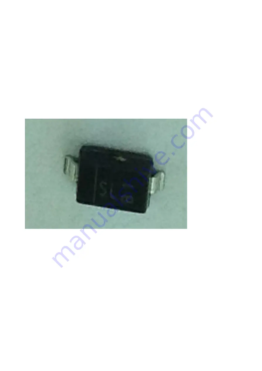
Next, install the two 1N5819 diodes, D1 & D2. Remove the diodes from the tape, & place them in
the bowl. You'll notice that unlike the resistors and capacitors you've installed already, these diodes
have a metal tab protruding outwards at an angle from the device. When you solder the diode onto
the PCB, you want these metal tabs pointing downwards so that they're in contact with the pads on
the PCB.
In addition, unlike the components you've installed up to now, these are polarised devices, meaning
they must be installed on the PCB with the correct orientation. If you look at one closely, with the
tabs pointing downwards, you'll notice a line marked on the top of the package, with the line closer
to one of the tabs than the other. (The line may be faint, so the use of a magnifying glass or loupe
will help). The end of the diode marked with this line is known as the cathode. The PCB silk screen
around the pads for each of the diodes should have a marking identifying which pad the cathode end
should be installed to. If this identification isn't present, the cathode end of both diodes should be
installed on the pad nearest the edge of the PCB (see the picture below).
So, now you know which way the diode needs to be installed on the PCB, solder them using the
same technique as the previous components. It's recommended that once you solder one end of the
diode, double check you have the cathode end by the edge of the PCB, before committing to
soldering the other end.
MTM SimpleEQ 0805 build doc v1.1
Page 16
Illustration 17: Surface mount diode, showing line identifying cathode as
the left hand pin


