Multiva Cerex 300 Comfort Operation And Maintenance Manual Download Page 60


Number

Hydraulic hose

Colour code and

symbol

1.

Drawbar adjustment connection

2 male connectors of ½”

2.

Hydraulic connection of the coulter pressure

adjustment

2 male connectors of ½”

3.

Hydraulic connection for raising the machine to the

transport position

2 male connectors of ½”

4.

Hydraulic connection of the adjustment of the front

levelling board position

2 male connectors of ½”

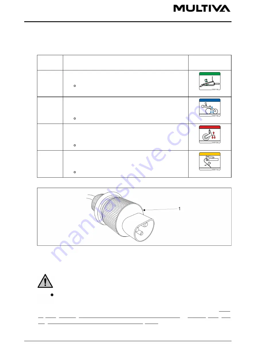
Figure. 5.3. - 61. Comfort controller power cable DIN 9680

6.  If  the  machine  is  equipped  with  a  Comfort  control  system,  plug  the  controller  power

cable (1) into the tractor cabin plug. 

DANGER

Ensure that the tractor is turned off and the key is removed from the ignition.

Ensure  the  cable  is  not  crushed  by  the  tractor's  rear  window.  Fasten  the  cable

properly so that it is not pinched during turns or lifting.  

7.  If  necessary,  straighten  the  machine  according  to  the  instructions  in  section  5.3.3.

Adjusting the lengthwise level of the machine with a turnbuckle or 5.3.4. Adjusting the

lengthwise level of the machine with a drawbar cylinder. 

Operation and maintenance manual
Cerex 300 and Cerex 400 Comfort

1.00

60 (187)

Summary of Contents for Cerex 300 Comfort

Page 1: ...Operation and maintenance manual Seed drill Cerex 300 and Cerex 400 Comfort Translation of the original manual EN...

Page 2: ...ontrol system 4 2 1 Control system components 4 2 1 1 Speed sensor 4 2 1 2 Seeding position sensor 4 2 1 3 Hopper level sensors 4 2 1 4 Tramline clutches 4 2 1 5 Tramline clutch extensions 4 2 1 6 Lin...

Page 3: ...gearbox 6 6 2 Preparations preceding hopper lling in a machine with a gearbox on the seed side or a dual gearbox 6 6 3 Preparations preceding hopper lling in a machine with a small seed hopper 6 6 4 A...

Page 4: ...ing the tightness of the wheel bolts of the wheel packer 7 1 2 4 Checking the tightness of coulter bolts 7 1 2 5 Checking the tightness of the working platform bolts 7 1 2 6 Checking the tightness of...

Page 5: ...he drawbar cylinder 7 2 14 Lubricating the turnbuckle 7 3 Cleaning 7 3 1 Cleaning the hoppers 7 3 2 Cleaning the small seed hopper 7 3 3 Cleaning the paint surface 7 3 4 Cleaning the coulter discs 7 3...

Page 6: ...ing wheel 7 9 5 Adjusting the scrapers 7 9 5 1 Adjusting the disc scraper 7 9 5 2 Adjusting the cover wheel scraper 7 10 Comfort control system maintenance 7 10 1 Manual calibration of the speed senso...

Page 7: ...en it is in a awless technical condition The seed drill must be used in accordance with regulations identifying hazards and following the safety and operating instructions Original Multiva spare parts...

Page 8: ...equipment on the Cerex 300 and Cerex 400 Back and front railings Working platform stairs on the left Sieves for fertiliser hopper Wheel drive from transport wheels Adjustable hopper dividers Covering...

Page 9: ...seed side Adjusting of fertiliser target rate machine with dual gearbox Available with the Comfort SeedPilot or SeedPilot ISOBUS control systems Available with machines equipped with a chain gear or g...

Page 10: ...hine in practical circumstances Damage compensation claims not concerning the machine itself as well as those concerning damages caused by misuse or incorrect adjustments of the machine will be reject...

Page 11: ...ther manufacturers The manufacturer is not liable for damage caused to other machines or equipment that result from the use of this machine The manufacturer reserves the right to develop or modify the...

Page 12: ...riod 5 Warranty does not cover damage caused by incorrect operation or maintenance in violation of the operating manual excessive loading or normal wear loss of income downtime other consequential or...

Page 13: ...Before adjusting the accessories make sure that the tractor is turned o the key is removed from the ignition and the parking brake is engaged Be careful not to crush or cut your hand or ngers in the f...

Page 14: ...ng a calibration test ensure that the tractor s parking brake is engaged the middle markers have settled into the transport position and their ball valves are closed Crushing hazard when lifting the s...

Page 15: ...NGER Never stand or sit on top of the seed drill or within its operating area during operation Minimum safe distance 5 m DANGER Inspect the condition of the seed drill at least visually before moving...

Page 16: ...ers are equipped with stoppers CAUTION Use original machine spare parts whenever servicing and repairing the seed drill Using generic parts will void the warranty CAUTION Collect oil waste and dispose...

Page 17: ...connection 1 pcs 4 Hydraulic connection of the adjustment of the front levelling board position 1 pcs 5 Coulter pressure scale 1 pcs 6 Crushing when connecting and disconnecting the seed drill minimum...

Page 18: ...s Figure 3 3 3 Right side labels of the seed drill Table 3 3 7 Right side labels of the seed drill 1 Falling hazard do not climb on top of the wheel 2 pcs at both ends of the working platform 2 Fallin...

Page 19: ...warning labels of the seed drill Table 3 3 8 Left side warning labels of the seed drill 1 Crushing and impact hazard when lifting and lowering the middle markers 2 pcs on both middle markers 2 Adjust...

Page 20: ...underneath the transmission cover 2 Adjustment scale None 0 pcs in a machine without a gearbox 1 pc in a machine with a gearbox on the seed side 2 pcs in a machine with a dual gearbox 3 Product calibr...

Page 21: ...fting and lowering the rear markers 2 pcs 2 Rear lights 2 pcs 3 Re ectors 2 pcs 4 Warning tape 2 pcs 5 Plate slow vehicle 1 pcs Figure 3 3 7 Seed drill hopper Table 3 3 11 Markings on the seed drill h...

Page 22: ...tion manual 1 pc 2 Warning tape 2 pcs on both markers of the machine 3 Label indicating the transmission oil to use only in models equipped with a transmission 1 pc Figure 3 3 9 Front platform labels...

Page 23: ...running a calibration test and servicing The ball valve of the middle marker is closed when the handle 1 is perpendicular to the hydraulic hose A Open the 2 middle marker ball valves 4 when moving the...

Page 24: ...ol system These instructions describe the Lykketronic area counter and the Comfort control system 4 1 Lykketronic area counter 4 1 1 Counter components Figure 4 1 1 11 Area counter components 1 Displa...

Page 25: ...mission The 3 metre cable 4 is connected to the machine frame The 5 metre connecting cable 3 is connected to the 3 metre cable 4 1 2 Counter buttons and display Figure 4 1 2 13 Area counter 1 Display...

Page 26: ...h Press the C key repeatedly until the value is 0 4 1 3 2 Setting the value of advance The advance is set to 150 0 cm The value is entered in centimetres 1 Press the C key repeatedly until the advance...

Page 27: ...splay shows the number of the program version The device checks the condition of the batteries If the display shows text bL and the device switches o change the batteries If text bL ashes during use t...

Page 28: ...riggered in the controller within 7 seconds 4 2 1 2 Seeding position sensor Figure 4 2 1 2 15 Seeding position sensor The seeding position sensor 1 recognises when the machine is in the transport or s...

Page 29: ...hopper and one in the fertiliser hopper on the left side of the machine Hopper level sensors are also available as an accessory for the right hand side hoppers of the machine in which case the total...

Page 30: ...The clutch can be used to disconnect one feeder Figure 4 2 1 4 18 Notched feeder roller The tramline clutch comes with one notched feeder roller 1 as a standard feature When the tramline clutch is po...

Page 31: ...e right a machine equipped with a gearbox on the seed side On the right a machine with a dual gearbox A LINAK linear actuator 3 6 is used for remote control A pointer 2 5 indicates the fertiliser feed...

Page 32: ...eft and right 4 Stopping the tramline counter See section 6 3 3 Using the tramline counter 5 Changing the page When on the MAIN screen of the user interface go to the next screen SHFT by holding down...

Page 33: ...get rate 5 Mode and counter of tramline clutches See section 6 3 3 Using the tramline counter 6 User interface screen number SHFT adjustment and rotation tab Figure 4 2 3 23 SHFT adjustment and rotati...

Page 34: ...rate performed ha h Instructions on use of the area counter use can be found in section 6 3 6 Area counter use Setup screen Figure 4 2 3 25 Setup screen 1 Product calibration 2 User setup 3 Factory se...

Page 35: ...n 2 to return to the previous screen 1 Move the cursor to User setup 1 and open the screen by pressing the OK button 4 Figure 4 2 4 1 27 User setup 1 Display Adjusting the display brightness 2 Customi...

Page 36: ...ontrol target rate adjustment step Figure 4 2 4 1 28 Adjusting the fertiliser remote control target rate adjustment step 1 Press the OK button 1 2 Set the new target rate adjustment step using the up...

Page 37: ...sensor 3 Speed sensor calibration See section 7 10 2 Calibration of the speed sensor while driving 4 T Factor Electric fertiliser control calibration value which varies according to the calibration te...

Page 38: ...2 Press the right button 3 Figure 4 2 4 1 31 Setting the number of passes and selecting tramlines 3 Set the number of passes Count 1 using the arrow buttons 4 Press the SET button 3 The pass Bout 2 nu...

Page 39: ...is 5 this making the spray width 4 20 m Tramlines are made on the third pass Setting alarms Figure 4 2 4 1 33 Alarms 1 Seed hopper level sensor The alarm is triggered when the seed hopper is empty 2...

Page 40: ...he working position and the tractor is not moving The driving speed begins to ash on the MAIN screen 6 X 1 Disabled The alarm is not activated 7 Voltage The alarm is triggered when the voltage falls b...

Page 41: ...e wheel packer only when the machine is on a level surface Figure 5 1 1 35 Lifting the wheel packer 1 Place the wheel packer 1 to the centreline and to the front of the machine and attach the lifting...

Page 42: ...e 5 1 1 37 Hydraulic hoses and electrical wires 6 Open the fastening screw 3 of the tube mounts and remove the top 4 7 Draw the hydraulic hoses through the guide 1 and on both sides of the cylinder br...

Page 43: ...ylinder retract 10 Connect the hydraulic hoses 3 6 Connect the hydraulic hoses of the drawbar cylinder only when the drawbar cylinder is installed 11 Push the hoses back towards the drawbar to elimina...

Page 44: ...rawbar cylinder Number Component Quantity 1 Locking pin 8x71 2 pcs 2 Pin 45x110 2 pcs 3 Washer M45 4 pcs 1 Replace the washer 3 and fasten the drawbar cylinder to the seed drill with a mounting pin 2...

Page 45: ...ce with the cotter 3 3 Repeat steps 1 2 for the second attachment point of the turnbuckle 5 1 4 Mounting the front levelling board The front levelling board is an accessory Using the front levelling b...

Page 46: ...weighs 250 kg 2 Follow the mounting instructions for the Cerex 300 or Cerex 400 Mounting the front levelling board on a Cerex 300 Figure 5 1 4 42 Mounting the front levelling board on a Cerex 400 Num...

Page 47: ...Component Quantity 1 Hex screw M24x60 7 pcs 2 Washer M24 26 pcs 3 Locking nut M24 13 pcs 4 Hex screw M24x75 3 pcs 5 Shim 5 pcs 6 Hex screw M24x120 3 pcs 1 Raise the front levelling board using lifting...

Page 48: ...the markers on the marker axle on both sides of the seed drill by using components 1 6 Tighten the bolts of the markers so that there is no clearance 5 1 6 Removing the transport supports Once the fr...

Page 49: ...s 2 from both sides of the seed drill 5 1 7 Mounting the scraper The scraper is an accessory Figure 5 1 7 46 Mounting the scraper Number Component Quantity 1 Hex screw M16X50 6 pcs 2 Washer M16 12 pcs...

Page 50: ...nting the rear harrow The rear harrow is an accessory DANGER The mounting of the rear harrow requires two people DANGER Use a hoisting accessory when mounting the rear harrow Figure 5 1 8 47 Mounting...

Page 51: ...ed drill with shackles 1 3 Figure 5 1 8 49 Lifting the rear harrow 3 Tie a lifting sling 1 around the tube 2 DANGER Ensure that the capacity of the lifting sling and the lifting device is su cient The...

Page 52: ...he clamps 6 5 Attach the rear harrow tube to the rear harrow arms by fastening the clamp with washers 1 a hex screw 2 and a locking nut 5 Tighten the bolts of the rear harrow so that there is no clear...

Page 53: ...device is su cient The rear markers weigh 75 kg 2 Lift the rear markers with a lifting sling 1 through the frame 2 and place the frame so that the rear marker arms 3 5 are between the front levelling...

Page 54: ...4 and locking nuts 1 7 4 Repeat step 3 for the second attachment point Figure 5 1 9 53 Mounting rear marker cylinders Number Component Quantity 1 Pin 24 4 pcs 2 Washer M24 4 pcs 3 Linchpin 4 pcs 5 Pi...

Page 55: ...3 Washer M8 8 pcs 4 U bolt 4 pcs For transport the rear railing 1 of the working platform has been turned inward 1 Open the bolts of the rear railing of the working platform 2 Turn the railing outwar...

Page 56: ...end railing with washers 2 U bolt 3 and locking nuts 1 5 Repeat step 4 for the second attachment point 5 2 Commissioning 5 2 1 Installing the Lykketronic area counter Figure 5 2 1 56 Installing the ar...

Page 57: ...ation where view is not obstructed but where the display is easily viewable by turning one s glance while driving Ensure that the cable is su ciently long to reach the display fastening spot 4 Snap th...

Page 58: ...drill The minimum safe distance 5 m Exercise extreme caution when there are personnel near the seed drill and tractor giving instructions on connecting and disconnecting Wear protective gloves when co...

Page 59: ...nction connections 5 Connect the hydraulic hoses of the seed drill to the tractor s double acting spool valve 6 7 DANGER Ensure that the tractor is turned o and the key is removed from the ignition DA...

Page 60: ...chine is equipped with a Comfort control system plug the controller power cable 1 into the tractor cabin plug DANGER Ensure that the tractor is turned o and the key is removed from the ignition Ensure...

Page 61: ...rdance with the instructions in section 5 3 6 Ensuring the steerability of the tractor 11 When driving on a eld for the rst time set the middle markers according to the instructions given in section 5...

Page 62: ...ground support 2 Move the ground support up or down by the lever 1 3 Lock the ground support in the mounting hole Attach the mounting pin and the cotter The upper mounting hole 2 locks the ground supp...

Page 63: ...the handle 1 and check visually that the machine is straight 5 When the machine is straight turn the plate downward to engage the lock 5 3 4 Adjusting the lengthwise level of the machine with a drawb...

Page 64: ...move slats if needed until the machine is straight 5 3 5 Using the machine li ing circuit ball valve Figure 5 3 5 69 Lifting circuit ball valves DANGER Close the lifting circuit ball valve 2 before st...

Page 65: ...ight control system the height of the lifting device may change based on the load and impact the seeding depth 5 3 7 Adjusting the middle markers Figure 5 3 7 70 Adjusting the middle markers 1 Loosen...

Page 66: ...pressure in accordance with section 7 1 3 Checking tyre pressure 6 Ensure that the machine is clean If necessary clean the machine in accordance with section 7 3 Cleaning 7 Visually check that the bol...

Page 67: ...the machine to the working position 1 Open the machine lifting circuit ball valve in accordance with section 5 3 5 Using the machine lifting circuit ball valve 2 If the machine is equipped with middle...

Page 68: ...is the default operating mode Normal mode Figure 6 3 1 75 Normal mode The machine and middle markers operate normally The counters and switching of the middle marker side will be operational whenever...

Page 69: ...r interface The function infobox 2 also ashed on the screen Counter stop mode Figure 6 3 1 77 Counter stop mode Corresponds with the Stop tramlines function See section 6 3 3 Using the tramline counte...

Page 70: ...lecting middle markers 1 Select a middle marker using the arrow buttons Press the left arrow button to activate the left middle marker Press the right arrow button to activate the right middle marker...

Page 71: ...LINE COUNTER button several times in a row until the correct number of tramlines is set The number of tramlines will increase at rst and then start from 1 again Stopping the tramline counter Figure 6...

Page 72: ...n 1 Press the SET button 2 The rst number starts to ash 2 Change the value by pressing the up down arrow buttons 3 Con rm the value by pressing right arrow button 4 Repeat steps 2 3 for other numbers...

Page 73: ...get rate by the set step default 5 The change in rate is displayed as a percentage 2 on the screen Instructions on setting the step are provided in section 4 2 4 1 User setup 6 3 6 Area counter use Fi...

Page 74: ...e ective roller length with screw type control wheels The feeders are powered by the machine s left running gear via a chain In the feeder there is a shut o plate between the feeder chamber and the h...

Page 75: ...Figure 6 5 87 Seeding table for machines with standard equipment Figure 6 5 88 Seeding table small seed hopper Operation and maintenance manual 1 00 Cerex 300 and Cerex 400 Comfort 75 187...

Page 76: ...Figure 6 5 89 Seeding table seed gearbox 1 Figure 6 5 90 Seeding table seed gearbox 2 Operation and maintenance manual Cerex 300 and Cerex 400 Comfort 1 00 76 187...

Page 77: ...Figure 6 5 91 Seeding table seed gearbox 3 Figure 6 5 92 Seeding table seed and fertiliser gearbox 1 Operation and maintenance manual 1 00 Cerex 300 and Cerex 400 Comfort 77 187...

Page 78: ...tiliser gearbox 3 6 6 Preparations preceding hopper lling 6 6 1 Preparations preceding hopper lling in a machine without a gearbox 1 Ensure that the stability of the tractor and seed drill combination...

Page 79: ...culating the stability of the tractor seed drill combination 2 Ensure that the hopper is empty clean and dry If needed clean the hopper in accordance with section 7 3 1 Cleaning the hoppers 3 Check th...

Page 80: ...osition in the feeder units of the small seed hopper 6 6 4 Adjusting the hopper divider Figure 6 6 4 95 Adjusting the hopper divider DANGER Before adjusting the divider ensure that the hoppers are emp...

Page 81: ...erent divider positions on the Cerex 400 Cerex 400 Seed L Fertiliser L Total L 1 1 500 3 300 4 800 2 1 700 3 100 4 800 3 1 850 2 950 4 800 4 2 050 2 750 4 800 5 2 200 2 600 4 800 6 2 350 2 450 4 800...

Page 82: ...e control wheel 1 is for seeds and control wheel 2 is for fertiliser If the machine is equipped with adjusting of fertiliser target rate there is no fertiliser control wheel The seed quantity increase...

Page 83: ...h the chain gears and the ne adjustment by adjusting the width of the roller Figure 6 6 6 98 Changing the chain gears and chain 1 Loosen the tensioning wheel 1 2 Remove the cotter 2 from the chain gea...

Page 84: ...ntity increases when the value of the adjustment scale increases and vice versa Adjust the width of the feeder roller in accordance with section 6 6 5 Adjusting the width of the feeder roller When see...

Page 85: ...lever is adjusted from the working platform 6 6 9 Adjusting the shut o plate position Figure 6 6 9 102 Adjusting the shut o plate position 1 Adjust the position of the shut o plates 1 of the feeders i...

Page 86: ...de of the small seed hopper The seeding tables are provided in section 6 5 Seeding quantities The main scale of seeding quantity is on the control wheel lock 2 and the secondary scale on the control w...

Page 87: ...n in the feeder units of the small seed hopper 1 Change the position of the control lever 1 on the notch scale Figure 6 6 11 106 Bottom ap positions in the feeder units of the small seed hopper When s...

Page 88: ...escue and ryegrass the shut o plate must be closed two notches When seeding clover the shut o plate must be closed three notches All shut o plates should be in the same position 6 7 Filling the hopper...

Page 89: ...he seed drill or inside the hoppers when the hoppers are being lled DANGER Avoid breathing seed dressing dust and fertiliser dust The seed dressing causes a serious health risk DANGER Read the materia...

Page 90: ...hoppers In the autumn or after rain the fertiliser may absorb humidity in the feeders changing fertiliser uidity For this reason it is good to monitor that fertiliser or seed ow evenly from all feeder...

Page 91: ...tate the axle counterclockwise by 1 round per second using the calibration test crank An area of 100 m is obtained by turning the crank 22 rounds on the Cerex 300 and 16 5 rounds on the Cerex 400 7 Pu...

Page 92: ...in 2 of the small seed hopper 5 Attach the calibration test crank 3 to the calibration test axle Turn the crank unti an even ow of fertiliser comes out of all feeders Empty the calibration trays 6 Rot...

Page 93: ...oves when the feeder shaft is rotating to prevent the feeders from being damaged 1 Raise the transmission cover Figure 6 8 3 113 Calibration test with adjusting of fertiliser target rate On the left a...

Page 94: ...the OK button 2 Figure 6 8 3 115 Fertiliser target rate 6 Change the fertiliser target rate 1 by pressing the SET button 2 Figure 6 8 3 116 Setting the fertiliser target rate The rst number starts to...

Page 95: ...bration test crank On the left a machine without a gearbox and on the right a machine equipped with a gearbox 12 Attach the calibration test crank 1 to the calibration test shaft Turn the crank until...

Page 96: ...ies they now contain The calibration test quantity obtained corresponds to the area of 100 m so the quantities for a hectare will be hundredfold Figure 6 8 3 120 Setting the weighing result The weighi...

Page 97: ...f fertiliser target rate machine with dual gearbox This section contains instructions on running calibration tests when using the adjusting of fertiliser target rate in Comfort control system If the m...

Page 98: ...ays are aligned with the feeders and their lock 5 is turned to the side 4 Remove the cotter pin 3 on the seed side from the feed shaft chain gear If the machine is equipped with a small seed hopper re...

Page 99: ...rst number starts to ash 7 Change the value by pressing the up down arrow buttons 8 Con rm the value by pressing right arrow button One of the numbers starts to ash 9 Repeat steps 7 8 for the second...

Page 100: ...e quantities they now contain The calibration test quantity obtained corresponds to the area of 100 m so the quantities for a hectare will be hundredfold Figure 6 8 4 128 Entering the weighing result...

Page 101: ...tion 21 Put the transmission cover back in place 6 8 5 Seed calibration test in a machine without a gearbox DANGER Shut o the tractor remove the key from the ignition and engage the parking brake befo...

Page 102: ...ity obtained corresponds to the area of 100 m so the seeding quantities for a hectare will be hundredfold If the weighing result does not match the desired quantity adjust the length of the roller in...

Page 103: ...r second using the calibration test crank An area of 100 m is obtained by turning the crank 22 rounds on the Cerex 300 and 16 5 rounds on the Cerex 400 7 Pull out the calibration trays and weigh the q...

Page 104: ...es Figure 6 8 7 132 Feeder funnel assembly of the small seed hopper 1 Open the four locking pins 2 of the feeder funnel assembly 2 Set the feeder funnel assembly in the calibration test position by fo...

Page 105: ...100 m is obtained by turning the crank 22 rounds on the Cerex 300 and 16 5 rounds on the Cerex 400 7 Pull out the calibration trays of the small seed hopper and weigh the quantities they now contain T...

Page 106: ...ter by means of the covering wheel The label 1 shows the seeding depths in millimetres Figure 6 9 135 Adjusting the seeding depth of the coulter 1 Remove the cotter pin 1 2 Insert the pin 2 in the hol...

Page 107: ...80 kg On light soil use smaller pressure and on hard soil greater pressure The pressure should be rst set too high and then lowered down if needed rather than adjusting the pressure too low in the rs...

Page 108: ...n the appropriate hole 3 There are three holes to choose from When the pin is in the bottom hole the rear harrow is in an upright position This position enables the rear harrow to move the most soil W...

Page 109: ...igher the position of the front levelling board 6 13 Controlling the seeding depth 1 Drive at the normal seeding speed 8 12 km h approximately 10 metres and stop 2 Stop the tractor switch o the power...

Page 110: ...mpty the seed or fertiliser is directed to the calibration tray through the feeders and the tray is emptied Instructions on performing the calibration test are provided in chapter 6 8 7 Calibration te...

Page 111: ...tion test of the small seed hopper 6 16 2 Emptying the small seed hopper through pipes Figure 6 16 2 141 Bottom ap of the small seed hopper open 1 Open the small seed hopper bottom ap by turning the c...

Page 112: ...r DANGER Depressurise the hydraulic system before disconnecting it Follow the tractor manufacturer s instructions DANGER Wear protective gloves when disconnecting the hydraulics 4 Disconnect the drawb...

Page 113: ...400 has 3 lifting cylinders 1 3 The stoppers are placed on the outermost cylinders 1 3 5 Ensure that the value of coulter pressure adjustment is 1 Instructions on the adjustment of coulter pressure ar...

Page 114: ...1 3 The stoppers are placed on the outermost cylinders 1 3 Place a stand or other support under the machine Never go under the machine that is not propped up DANGER Close the machine lifting circuit...

Page 115: ...X 7 1 3 Checking tyre pressure X X 7 1 4 Checking the bearing clearance of the wheel packer hubs X 7 1 5 Checking the tightness of the transmission chains X X 7 1 6 Checking the tightness of the wheel...

Page 116: ...bolts M20x1 5 1 on the transport wheels are tight There are 60 wheel bolts on the Cerex 300 and 78 on the Cerex 400 Tighten the bolts if needed If the gap between the tyres is narrow tighten the bolt...

Page 117: ...ly 1 Check that all the 24 ange bearing bolts M16 1 of the transport wheel assembly are tight Each bearing has four bolts There are six bearings Tighten the bolts if needed If the gap between the tyre...

Page 118: ...packer bar 1 2 Detach the wheel packer bar by lifting it Figure 7 1 2 3 148 Wheel bolts of the wheel packer 3 Check that all the 20 wheel bolts M18 1 of the wheel packer are tight Tighten the bolts if...

Page 119: ...Coulter shank bolts 1 Check that coulter shank bolts M20 1 are tight There are 12 coulter shank bolts on the Cerex 300 and 18 on the Cerex 400 If needed tighten the bolts to torque 300 Nm Operation a...

Page 120: ...nuts to torque 100 Nm Figure 7 1 2 4 151 Bolts of the coulter covering wheel and depth adjustment 3 Check that all the coulter covering wheel bolts M16 3 4 are tight There are 40 coulter covering whee...

Page 121: ...tform bolts 1 Check that the 6 bolts M12 2 of the working platform are tight Tighten the bolts if needed 2 Check that the 4 bolts M16 1 near the lifting cylinder are tight Tighten the bolts if needed...

Page 122: ...eel packer available as an accessory is 3 0 bar 7 1 4 Checking the bearing clearance of the wheel packer hubs Figure 7 1 4 155 Checking the bearing clearance of the wheel packer hubs 1 Insert a bar 1...

Page 123: ...down and lifting it up with your nger The maximum allowed chain de ection A is 10 mm If needed tighten the chains in accordance with section 7 5 1 Tightening the chains in a machine without a gearbox...

Page 124: ...cover Figure 7 1 5 3 158 Checking the tightness of the transmission chains in a machine with a dual gearbox 2 Check the de ection of the gearbox chain 2 fertiliser side chain 3 and seed side chain 1 b...

Page 125: ...needed tighten the chains in accordance with section 7 5 4 Tightening the transmission chains of the small seed hopper 3 Put the transmission cover back in place 7 1 6 Checking the tightness of the w...

Page 126: ...ve clutch The clutch should be inspected once per year seeding season Figure 7 1 7 162 Inspecting the clutch 1 Check the clearance of the exible coupling element of the clutch 1 Check the clearance of...

Page 127: ...usting tighten the locknut 1 7 1 9 Checking the condition of hydraulics 1 Check the tightness of the hydraulic system 2 If needed tighten the connections 3 Make sure that the hoses are intact and have...

Page 128: ...he towing eye 7 1 12 Checking the gearbox oil level Figure 7 1 12 165 Gearbox oil level 1 Check the oil level of the gearbox es The oil level should be at 40 45 mm from the bottom of the ll hole 1 If...

Page 129: ...ean the discs if necessary in accordance with section 7 3 4 Cleaning the coulter discs If the disc still does not rotate replace the disc if needed in accordance with section 7 9 2 Replacing a coulter...

Page 130: ...d axles do not rotate 7 2 Lubrication After the commissioning of the machine all lubrication points should be lubricated after the rst 10 hectares The disc coulters are equipped with self lubricating...

Page 131: ...4 7 2 5 Lubricating the rear axle mounting X 2 7 2 6 Lubricating the wheel axle bearings X 6 7 2 7 Lubricating the lifting cylinder X Cerex 300 2 Cerex 400 6 7 2 8 Lubricating the towing eye X 7 2 9...

Page 132: ...and not only in the reel 3 Put the transmission cover back in place 7 2 2 2 Lubricating the chains in a machine with a gearbox on the seed side 1 Raise the transmission cover Figure 7 2 2 2 169 Lubric...

Page 133: ...etween the chain discs and not only in the reel 3 Put the transmission cover back in place 7 2 2 4 Lubricating the small seed hopper transmission chains 1 Raise the transmission cover Figure 7 2 2 4 1...

Page 134: ...that oil also ows between the chain discs and not only in the reel 3 Reattach the housing cover and fasten the two fastening bolts of the cover Always use new locknuts to fasten 7 2 3 2 Lubricating wh...

Page 135: ...fasten the two fastening bolts of the cover Use new locknuts to fasten 7 2 4 Lubricating the coulter pressure cylinder Figure 7 2 4 175 Lubricating the coulter pressure cylinder 1 Lubricate the coulte...

Page 136: ...rear axle mounting 1 The link bushings are located in the rear corners of the hopper on both sides of the seed drill 7 2 6 Lubricating the wheel axle bearings Figure 7 2 6 177 Wheel axle bearings 1 L...

Page 137: ...he Cerex 300 and 3 lifting cylinders 1 3 on the Cerex 400 There is a grease nipple at the top and bottom of the lifting cylinder 7 2 8 Lubricating the towing eye Figure 7 2 8 179 Towing eye 1 Clean th...

Page 138: ...is a grease nipple at the top and bottom of the middle marker cylinder 7 2 10 Lubricating the rear marker cylinders Figure 7 2 10 181 Rear marker cylinders 1 Lubricate the 2 marker cylinders 1 There i...

Page 139: ...two lubrication nipples 2 4 The vertical pin has two lubrication nipples 1 3 2 Lubricate the two pins of the wheel packer bar There is one lubricating nipple 5 in both pins of the wheel packer bar Fi...

Page 140: ...e wheel hubs 6 Replace the wheel packer bar and lock the bar with cotters 7 2 12 Lubricating the front levelling board cylinders Figure 7 2 12 185 Front levelling board cylinders 1 Lubricate the 2 fro...

Page 141: ...cylinder 1 There is a grease nipple at the top and bottom of the drawbar cylinder 7 2 14 Lubricating the turnbuckle Figure 7 2 14 187 Turnbuckle 1 Lubricate the turnbuckle 5 The turnbuckle has 4 lubr...

Page 142: ...ide feed units in the front of the seed drill by turning the control lever 1 downward 2 Open the bottom ap of the seed side feeder units in the back of the seed drill in the same way The back bottom a...

Page 143: ...he variety to be seeded changes and at the end of the seeding season Figure 7 3 2 190 Bottom ap open 1 Open the bottom ap of thr feeder unit by turning the control lever 1 downward Figure 7 3 2 191 Cl...

Page 144: ...washing The painted surface can be protected with a light application of oil using protective oil intended for the purpose Entry of protective oil on rubber and plastic parts should be avoided 7 3 4...

Page 145: ...roller after the adjustment clean the roller grooves with a wooden stick 7 3 6 Cleaning the small seed hopper feeder units Wear protective goggles and protective gloves when cleaning the feeder Clean...

Page 146: ...s DANGER Ensure that the seed drill is set securely in place and that the lifting cylinder is in the transport position Ensure that the seed drill cannot move in any direction DANGER The wheel set dem...

Page 147: ...lace the cylinders on the working platform Figure 7 4 1 197 Demounting the rear harrow 3 If the machine is equipped with a rear harrow demount it by removing the bolts 2 washers 3 4 and nuts 5 of the...

Page 148: ...hen demounting the rear harrow Tie a lifting sling 1 around the tube 2 Figure 7 4 1 199 Transport supports 4 Install the transport supports 2 on both sides of the seed drill with M20x50 bolts 1 Operat...

Page 149: ...d the outermost wheel set to prevent the middle wheel set from falling Ensure that the bolts do not penetrate the back of the plate 2 3 If you are demounting the left hand side wheel set turn the bolt...

Page 150: ...omes loose 7 4 2 Disassembling a wheel set Figure 7 4 2 203 Detaching a ange bearing 1 Open the locking screw 1 2 Remove the ange bearing 2 from the axle Use an extraction tool to detach the bearing D...

Page 151: ...should be demounted from the side of the centre tyre bolts in the pack 7 4 3 Mounting a wheel set 1 Clean the surfaces before installing a wheel set 2 Clean the threads of bolts Figure 7 4 3 205 Moun...

Page 152: ...w locknuts 2 Remove the transport supports 3 If necessary mount the scraper in accordance with section 5 1 7 Mounting the scraper the rear harrow in accordance with section 5 1 8 Mounting the rear har...

Page 153: ...to the right 5 Tighten the tensioning wheel 6 Tighten the fertiliser side chain by pushing the chain gear 3 down 7 Tighten the chain gear nut 3 8 Check the chains for de ection The de ection should b...

Page 154: ...ightening the chains in a machine with a dual gearbox 2 Loosen the gearbox chain 3 by loosening the nut of the chain gears 1 5 3 Loosen the fertiliser side chain 2 by loosening the nut of the chain ge...

Page 155: ...chain 4 by loosening the three bolts of the bearing housing 3 5 Tighten the chain by moving the bearing downward Tighten the 3 bolts 2 of the bearing housing 6 Tighten the chain 6 by moving the casing...

Page 156: ...locking pin 3 of the slotted nut 2 on the axle 4 Tighten the nut by turning the wheel simultaneously until light resistance is felt in the bearing 1 5 Loosen the nut until the locking pin ts into the...

Page 157: ...hain 2 Loosen the mounting nut 1 located at the end of the chain gear 3 Tighten the wheel drive chain 2 by moving the gear towards the transmission axle 4 Tighten the mounting nut 1 of the chain gear...

Page 158: ...crew 2 in the clutch body 2 Separate the components of the clutch 1 by pulling the clutch on the axle towards the wheel drive mechanism 3 Detach the exible coupling element 3 of the clutch 7 7 2 2 Ins...

Page 159: ...2 7 8 Towing eye 7 8 1 Replacing the towing eye 7 8 1 1 Detaching the towing eye Figure 7 8 1 1 218 Towing eye 1 Remove the 12 bolts 1 of the towing eye 2 Remove the towing eye 2 7 8 1 2 Installing th...

Page 160: ...fore servicing 7 9 1 Replacing a coulter 7 9 1 1 Demounting a coulter Figure 7 9 1 1 220 Disconnecting coulter hoses 1 Open the hose clamps 1 4 of the hoses 2 3 at the end of the coulter and pull the...

Page 161: ...the coulter Do not remove the bolt right away but loosen all four bolts equally 4 Remove the bolts installation plate 2 and the four dampening rubbers 3 5 Move the coulter from its location 7 9 1 2 In...

Page 162: ...tighten the bolts evenly to eliminate any gap between the mounting plates Use new locknuts with a strength rating of 10 to fasten Figure 7 9 1 2 223 Connecting coulter hoses 6 Connect the hoses 2 3 i...

Page 163: ...Figure 7 9 2 1 224 Detaching a disc 1 Remove the mounting bolts 2 5 pcs of the disc 1 The disc will fall o Replace the bearing when changing a disc Figure 7 9 2 1 225 Detaching the bearing housing 2 L...

Page 164: ...dance with section 7 9 3 2 Installing a bearing Figure 7 9 2 2 226 Installing the bearing housing 1 Clean the plane surface 3 of the bearing housing 2 Mount the bearing housing onto the coulter axle 3...

Page 165: ...7 9 3 Replacing a coulter bearing 7 9 3 1 Detaching a bearing Remove the coulter disc in accordance with section 7 9 2 1 Detaching a disc Figure 7 9 3 1 228 Bearing seal and shim 1 Detach the bearing...

Page 166: ...housing 1 Detach the bearing from the back of the bearing housing using a clamp 7 9 3 2 Installing a bearing Figure 7 9 3 2 230 Installing a bearing 1 Clean the bearing housing 1 2 Install the new be...

Page 167: ...bearing is changed 7 9 4 Replacing the coulter covering wheel 7 9 4 1 Demounting the covering wheel Figure 7 9 4 1 232 Demounting the covering wheel 1 Remove the locknut 1 of the covering wheel 2 and...

Page 168: ...and fasten it with a bolt M16x100 2 two washers M16 1 and nut M16 3 Use new locknuts when installing 7 9 5 Adjusting the scrapers 7 9 5 1 Adjusting the disc scraper DANGER Use caution the disc edges a...

Page 169: ...or inner plate at any point The disc must turn freely 3 Tighten the scraper fastening bolt 7 9 5 2 Adjusting the cover wheel scraper Figure 7 9 5 2 235 Cover wheel scraper 1 Loosen the two fastening...

Page 170: ...rst number starts to ash 3 Change the value by pressing the up down arrow buttons 4 Con rm the value by pressing the right arrow button 5 Repeat steps 3 4 for other numbers 6 Con rm the correction by...

Page 171: ...e end 5 Press the OK button 2 The new calibrated value 1 appears on the screen 6 Accept by pressing OK button 2 or rerun the calibration by pressing ESC button 3 Figure 7 10 2 240 New calibrated value...

Page 172: ...s The tramline fertiliser clutch is not working and no pulses are coming from the seed shaft Check that the shaft rotates Check the sensors The tramline seed clutch is not working and pulses are comin...

Page 173: ...is outside the T value limits On the Setup screen select 3 Factory Setup enter the PIN code 1234 select 2 Actuator Setup select STR as your Line Type setting select Line Factors set the T value manua...

Page 174: ...value and then accept it by pressing the OK button The value 0 00000 should now appear on the line Repeat the above and enter 0 40000 as the value The middle markers do not work automatically or in th...

Page 175: ...ndicated by the calibration test 1 The bottom ap position is incorrect 1 Check the position of the bottom ap in accordance with section 6 6 8 Adjusting the bottom ap position or section 6 6 11 Adjusti...

Page 176: ...ed 1 Open the machine lifting circuit ball valve in accordance with section 5 3 5 Using the machine lifting circuit ball valve 2 The quick coupling is open 2 Check the connection of the quick release...

Page 177: ...rmity 2 Hydraulic schematics 3 Electrical schematics 4 Connection socket according to SFS 2473 5 Calculating the stability of the tractor seed drill combination Operation and maintenance manual 1 00 C...

Page 178: ...0303 L1010001 Multiva FORTE FX400 starting from serial number 000 090304 L1010001 meet the requirements of Machinery Directive 2006 42 EC with respect to the construction of machinery Furthermore the...

Page 179: ...Hydraulic schematics Cerex 300 and Cerex 400 1 Hydraulic schematics Cerex 300...

Page 180: ...Hydraulic schematics Cerex 300 and Cerex 400 2...

Page 181: ...Hydraulic schematics Cerex 300 and Cerex 400 3 Hydraulic schematics Cerex 400...

Page 182: ...Hydraulic schematics Cerex 300 and Cerex 400 4...

Page 183: ...Electrical schematics Cerex 300 and Cerex 400 Comfort 1 Electrical schematics...

Page 184: ...Electrical schematics Cerex 300 and Cerex 400 Comfort 2...

Page 185: ...Electrical schematics Cerex 300 and Cerex 400 Comfort 3...

Page 186: ...Connection socket according to SFS 2473 1 L Left turn signal 2 54G Free 3 31 Ground 4 R Right turn signal 5 58R Right rear light lic plate light 6 54 Brake light 7 58L Left rear light...

Page 187: ...manual 2 See the implement manual 3 To be measured Figure 1 Calculating the stability of the tractor seed drill combination kg Tractor s dead weight 1 kg Front axle load of an empty tractor 1 kg Rear...

Reviews: