background image


43 


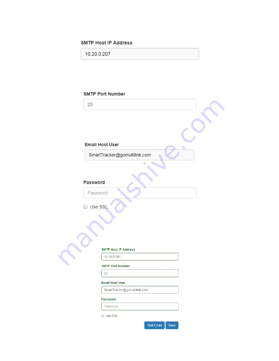
SMTP Host IP Address

:


 This item is the SMTP host server for which emails will be relayed to the recipients. This 

may be an IP address or a domain name. In this example, an IP address for the host’s 
email server is used. 


SMTP Port Number

:


 This text field is the SMTP port for which emails will be relayed. In this example, Port 25 is 

the authorized port that is used for email. Consult with the network administrator to deter-
mine the correct port number to use. 


Email Host User

:


 This is the Smart Tracker’s email address. The user may change the Smart Tracker email address 

to better represent the device. In this example, the username of the email address is 
“SmartTracker” and the domain portion is @gomultilink.com.  


Password

:


 Used for user authentication, if required, by the SMTP email host. The “Use SSL” and a valid email ad-

dress and password must be established by the network administrator for this field to be used.  


Saving Email Configuration Settings

:


When all information is input, click the “Save” button to save all changes. As with previous pages, all textboxes and 
options will illuminate Green to indicate the changes have be saved. 


Summary of Contents for 018-041-10

Page 1: ...Plant 440 366 6966 580 Ternes Avenue Fax 440 366 6802 Elyria Ohio 44035 USA Website www gomultilink com Manual Part No 018 041 A0 Revision 05 03 21 19 Installation and Operation Manual Smart Tracker R...
Page 2: ...ed by this installation and operation manual This device and its respective packages may be referenced using the part numbers listed below MODEL NUMBER PART NUMBER INPUTS OPTIONS Smart Tracker ST 01 0...

Page 3: ...ors 8 Controls Connections Indicators Section 4 Installation and Setup 9 Preparation Grounding Placement in the Enclosure Wiring Section 5 Startup Operation 11 Operation Instructions Front Panel LCD M...

Page 4: ...NING AVERTISSEMENT The statement following the WARNING heading alerts the equipment user of a condition or procedure that could result in interruption of service to the users or subscribers of the ser...

Page 5: ...ervice to the Smart Tracker without first removing and disconnecting AC power Only trained qualified personnel should attempt service and repair work on the Smart Tracker Ground Fault Protection The S...

Page 6: ...o any number of recipients with information regarding the event GPS location with mapping provides the exact location of each Smart Tracker that is deployed in the field All events that occur are kept...

Page 7: ...r Damaged Items If items are found to be damaged or missing contact the shipping company and a Multilink representative immediately All damage claims must be filed with the shipping company conveying...

Page 8: ...cts Phoenix Contact terminal plug 8 positions per plug 2 contacts per relay 12 30 AWG Tighten to 5 0 lb in Rated for 10A 250VAC 125VDC Input Contacts Phoenix Contact terminal plug Optically isolated i...

Page 9: ...kers or fuses with appropriate AIC amperes interrupting capacity rating should be placed between the AC utility source and the service entrance device for the Smart Tracker Where used the disconnect s...

Page 10: ...closure This Smart Tracker has been designed primarily for use within a cabinet or enclosure offering protection from outdoor weather entry of excessive dust dirt or moisture and from unauthorized con...

Page 11: ...AC circuit breaker serving the Smart Tracker to the ON position 3 Operate the Input circuit breaker to the RESET or position on the Smart Tracker and the Smart Tracker will begin its initial start up...

Page 12: ...otal AC Current Total current draw of all outlets currently active CURRENT 5 5A MULTILINK Internal Temperature This is the internal temperature of the unit Values may TEMPERATURE 75 00F display in eit...

Page 13: ...P address to allow for local configuration and control of the de vice The user should attach an Ethernet cable from a computer prior to powering the device to allow the Smart Tracker to recognize the...

Page 14: ...etwork and Sharing Center and select Change adapter settings from the left panel 6 Left click on the Local Area Connection and select Properties Click to highlight Internet Protocol Version 4 TCP IP a...

Page 15: ...acker 11 Open a preferred web browser and enter the default IP address of the Smart Tracker in the address box If the user has assigned a different IP address enter this IP address instead The Summary...

Page 16: ...y and input contact label names indicates the current state of the respective outlet relay or input contact Green indicates active or On Red indicates inactive or Off Operating parameters will automat...

Page 17: ...t and begin to reflect and maintain the current local date and time This feature as sumes the user s device is set to reflect the correct date and time User Log in and Authentication When navigating a...

Page 18: ...o save the new password A prompt will appear at the top of the page to confirm or deny the new password Control Tab When clicking the Control tab a drop down list appears with five options Outlets Rel...

Page 19: ...o turn on or off any or all of the outlets Textboxes are included to allow the user to rename each outlet to reflect the piece of equipment that may be attached to that respective outlet Outlet inform...

Page 20: ...let 1 is used as an example All subsequent outlets will act in the same manner re spectively When turning on Outlet 1 the user is prompted with a message asking if they want to perform the action Clic...

Page 21: ...ED for Outlet 1 will turn off on the front of the unit Renaming Outlets To rename any of the outlets and provide additional information the user may type a new name into the text box for the respectiv...

Page 22: ...on to save the action s that each outlet will perform Once saved the selected ac tion s will appear in grey under each respective outlet Refer to the Scheduling section of this user manual for step by...

Page 23: ...a low or high impedance signal that may be used by a traffic controller or device as indication that a specific event or action has taken place They may also be used to switch on or off power to a dev...

Page 24: ...shots Relay 1 is used as an example All subsequent relays will act in the same manner When turning On Relay 1 the user is prompted with a message asking if they want to perform the action Click Turn...

Page 25: ...r Additionally the LED for Relay 1 will turn off on the back of the unit Renaming Relays To rename any of the relays and provide additional information the user may type a new name into the text box f...

Page 26: ...ate Green to indicate the changes have been saved and a prompt at the top of the page will indicate the changes have been suc cessfully saved Once saved the new name for Relay 1 will be displayed on t...

Page 27: ...s a UPS system being activated Each input has two mating contacts for which to attach wiring When continuity is pre sent between the two contacts the input will indicate Green on the Inputs and Summar...

Page 28: ...nput 1 is used as an example All subsequent inputs will act in the same manner Input Contact Actions The Input 1 Actions box may include tasks that the user has created that are to be performed when t...

Page 29: ...e edit and remove actions Saving Input Changes Click the Save button to save any changes When the Save button is clicked all text boxes will illuminate Green to indicate the changes have been saved an...

Page 30: ...periodic event The user will also use this page to edit and remove the trigger actions and scheduled periodic tasks Creating a Trigger Action A trigger action is created by the user and may be used b...

Page 31: ...Number for the outlet or the relay for which the action will take place The user may select a single outlet or relay or may select All which will affect all outlets or all relays When All is select ed...

Page 32: ...Scheduling page The new action will be listed on the Scheduling page The action will list its action outlet or relay number as well as if a wait period applies to the action Editing Trigger Actions Ea...

Page 33: ...ch or turning off an outlet to shutdown equipment to reduce power consumption The user can create up to 1 000 sched uled events for each Smart Tracker unit and can edit or delete each scheduled event...

Page 34: ...e correct local time Refer to the Configuration page to select or verify the time zone of the unit Day of Week Day of the week can be used to select a single day Monday Sunday weekdays Monday Friday w...

Page 35: ...et at 12 00PM EST on Feb 3rd This example se lected Every Sunday for when to occur and this event will automatically update the date shown for the next reoccur ring event Editing Schedules Each of the...

Page 36: ...remove power from a Smart Tracker due to the AC circuit breaker All outlets relays and network connectivity will become inactive The Reboot option can be used to remotely restart the Smart Tracker if...

Page 37: ...nts for voltage current temperature and humidity If an external temperature and humidity sensor has been purchased the option to enable this feature is also found on this page Additional features such...

Page 38: ...ith a NTP server to automatically update the date and time Select the timezone that most accurately depicts the location of the unit NTP Server Each Smart Tracker must be able to automatically update...

Page 39: ...ng the alarm This feature is auto correcting Humidity High This threshold can be adjusted to indicate when the internal humidity of the Smart Tracker has ex ceeded its high threshold value When this o...

Page 40: ...tes When Ping is enabled the unit will attempt to contact another device on the network The frequency of Ping may be adjusted as necessary The default is ten minutes Ping Host Address This is the addr...

Page 41: ...to correcting High AC Voltage This threshold can be adjusted to indicate when the AC input voltage has exceeded its high threshold value When this occurs the Smart Tracker will send an email notificat...

Page 42: ...page the user can configure and test the email notification feature Email notifications require SMTP server information to be entered in order for the Smart Tracker to send emails to the list of recip...

Page 43: ...Host User This is the Smart Tracker s email address The user may change the Smart Tracker email address to better represent the device In this example the username of the email address is SmartTracke...

Page 44: ...isplay below the textbox To remove any one of the recipients from the list click the Delete button and the email address will be removed Testing Email Notification Settings With a valid email recipien...

Page 45: ...quire its network configuration from the network s DHCP server Once a connection is established the IP subnet mask and default gateway addresses are stored for display and use The de vice MAC address...

Page 46: ...t the static IP address chosen is not currently in use and the appropriate subnet mask and gateway are configured for the IP address selected The example below shows the factory default IP address sub...

Page 47: ...quired Each textbox and dropdown list will be de scribed below A Management Information Base MIB is required when using SNMP to communicate with the Smart Tracker It is available by contacting Multili...

Page 48: ...nd SET commands received by the Smart Tracker from the user s network man agement software or MIB browser Read is selected by default Enable v3 The following textboxes and dropdown lists are used for...

Page 49: ...on clicking the Save Reboot button SNMP Management Information Base MIB The Smart Tracker requires that a MIB file be loaded into the user s MIB browser or network management software suite in order f...

Page 50: ...download the respective Smart Tracker s configuration file for use in other Smart Trackers This feature is designed to speed up the configuration of several units as opposed to manual ly configuring e...

Page 51: ...will operate under the same configura tion settings including any name changes triggers actions and schedules Follow the instructions below to upload a configuration file 1 To upload a configuration...

Page 52: ...s required Click Upload Reboot to begin the upload 4 The upload will commence and then inform the user that the system is rebooting 5 After a few minutes refresh the webpage to confirm the upload has...

Page 53: ...rform a reboot Periodically Multilink will inform users that a firmware update is available to those using v 1 1 0 or later firmware Follow the instructions below to perform a firmware update 1 Click...

Page 54: ...pdate Reboot to begin the firmware update process 5 After the firmware update process has completed the user will be prompted that the Smart Tracker is rebooting After a few minutes refresh the webpag...

Page 55: ...acker Shutdown The Smart Tracker can be shutdown at anytime During shutdown the user will observe that the LCD is active The Smart Tracker contains a circuit that allows the unit to save the operating...

Page 56: ...network adapter settings are correct and within the same IP range as the unit Reset to factory IP using Enter button Date and Time are not accurate Date and time incorrect Verify NTP Server setting i...

Page 57: ...erating range Frequency 60Hz Nominal 5 DC Inputs 2 0 60VDC Digital Inputs 8 5VDC 10mA max switching 2 contacts per input Output Power Outlets 8 5 15R Relays 8 10A 250VAC max switching 2 contacts per r...

Reviews: