


Barring engine manually – Var-
iant B
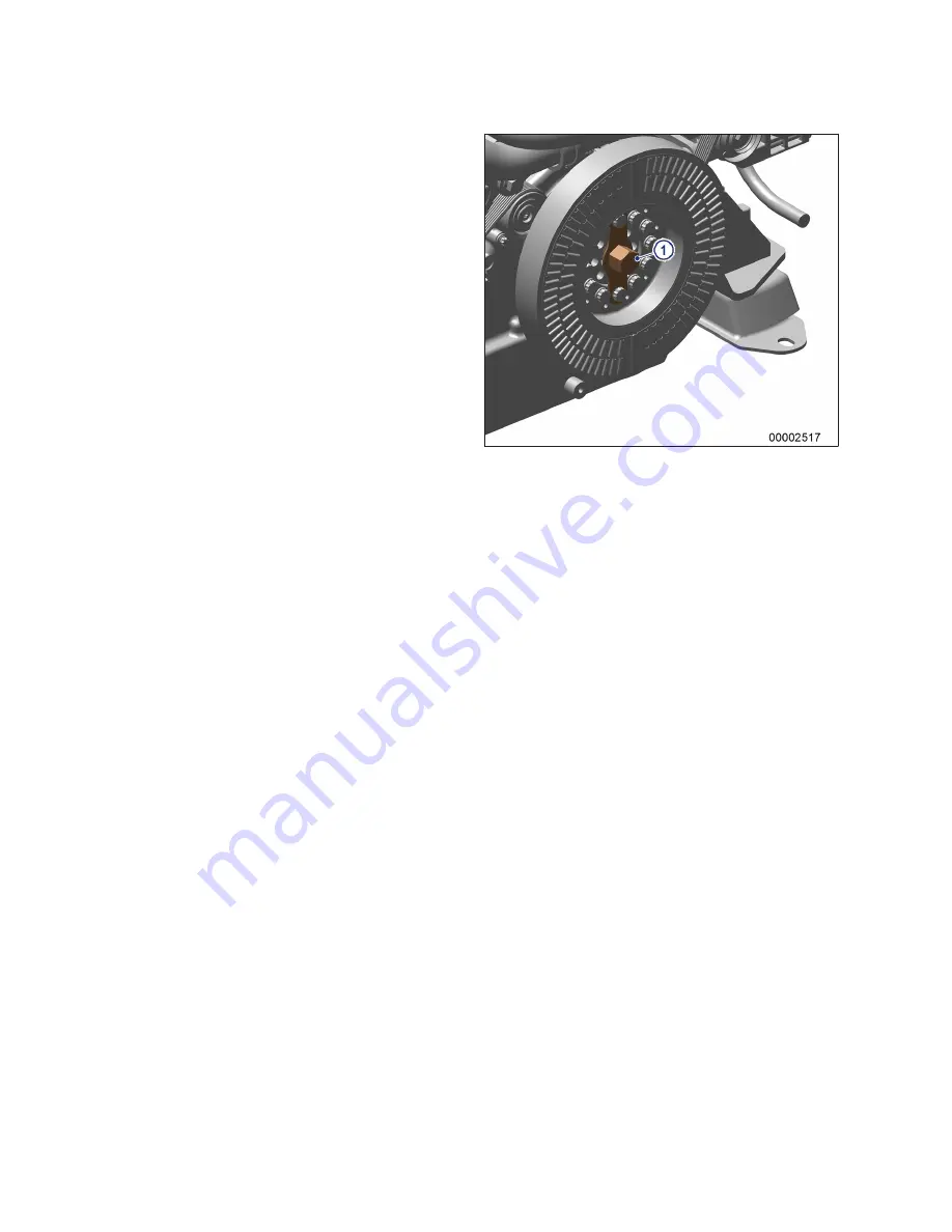
Note:
Barring gear (1) is installed on vibration
damper on engine free end.
1.
Fit ratchet with extension on barring gear
(1).
2.
Rotate crankshaft in engine direction of ro-
tation. Apart from the normal compression
resistance, there should be no resistance.
72 | Task Description | MS15029/01E 2015-06
TIM-ID: 0000043442 - 004


