background image

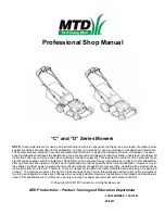
C and D series mowers

2

Safety

This Service Manual is meant to be used along with the Operator’s Manual.  Read the Operator’s Manual and 

familiarize yourself with the safety and operational instructions for the equipment being worked on. Keep a copy of 
the Operator’s Manual for quick reference. Operator’s manuals may be viewed for free at the brand support website.  
It will be necessary to have the complete model and serial number for the equipment.


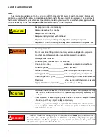
Be prepared in case of emergency:

Keep a fire extinguisher nearby

Keep a  first aid kit nearby

Keep emergency contact numbers handy

Replace any missing or damaged safety labels on shop equipment.

Replace any missing or damaged safety labels on equipment being serviced.

Grooming and attire:

Do not wear loose fitting clothing that may become entangled in equipment.

Long hair should be secured to prevent entanglement in equipment.

Jewelry is best removed.

Protective gear:  includes, but is not limited to

Clear eye protection                             while working around any machinery

Protective gloves                                  where necessary

Armored footwear                                 when working around any machinery

Hearing protection                                when working in noisy environments

Chemically resistant gloves                 when working with chemicals or solvents

Respirator                                              when working with chemical or solvents

Appropriate tinted eye protection        when cutting or welding

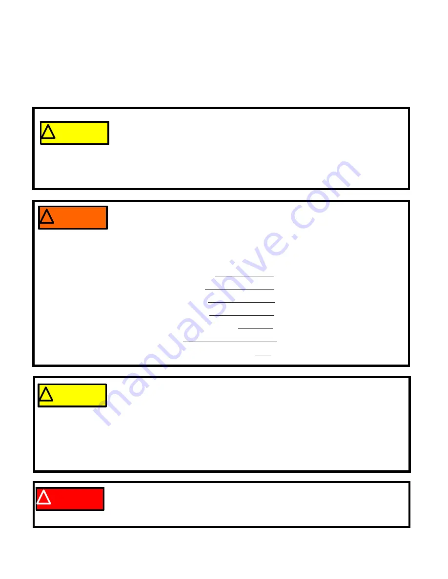
!  WARNING

!  WARNING

!  CAUTION

!  CAUTION

Remember that some hazards have a cumulative effect.  A single exposure may 
cause little or no harm, but continual or repeated exposure may cause very seri-
ous harm.

Clean spills and fix obviously dangerous conditions as soon as they are noticed.

Lift and support heavy objects safely and securely.

Be aware of your surroundings and potential hazards that are inherent to all 
power equipment. All the labels in the world cannot protect a technician from an 
instant of carelessness.

Exhaust fumes from running engines contain carbon monoxide (CO). Carbon monox-

ide is a colorless odorless gas that is fatal if inhaled in sufficient quantity. Only run engines 
in well ventilated areas. If running engines indoors, use an exhaust evacuation system with 
adequate make-up air ventilated into the shop. 

!   DANGER

!   DANGER

!  CAUTION

!  CAUTION

Summary of Contents for C series

Page 1: ...ts of the product s Oper ators Manual supplied with the equipment No liability can be accepted for any inaccuracies or omission in this publication although care has been taken to make it as complete and accurate as possible at the time of publication However due to the variety of outdoor power equipment and continuing product changes that occur over time updates will be made to these instructions...

Page 2: ......

Page 3: ... Cable 17 Drive Control Housing Assembly 19 Drive Control Housing Removal and Disassembly 20 Drive Clutch Control Cable Removal and Replacement 25 Drive Speed Control Cable Removal and Replacement 26 Chapter 4 Deck and transmission Trail Shield 27 Side Discharge Door Mulch Plug 28 Deckwash Fitting 30 Rear Grass Door 31 Front Wheels 33 Front Axle 36 Front Axle Cover 39 Handlebars 40 Transmission an...

Page 4: ...II ...

Page 5: ...red to complete a step Bullet points Indicate sub steps or points of interest without implying order or relative importance Disclaimer This manual is intended for use by trained professional technicians Common sense in operation and safety is assumed In no event shall MTD be liable for poor text interpretation or poor execution of the procedures described in the text If the person using this manua...

Page 6: ...around any machinery Protective gloves where necessary Armored footwear when working around any machinery Hearing protection when working in noisy environments Chemically resistant gloves when working with chemicals or solvents Respirator when working with chemical or solvents Appropriate tinted eye protection when cutting or welding WARNING WARNING CAUTION CAUTION Remember that some hazards have ...

Page 7: ...s regarding locking or lubrication Whichever method is more appropriate will be used In many cases both will be used so that the manual is handy as a quick refer ence guide as well as a step by step procedure guide that does not require the user to hunt for informa tion Lubricant quantity and specification may be noted in the part of the text that covers maintenance and again in the section that c...

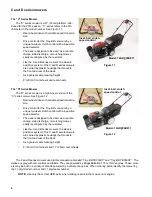
Page 8: ... Drive control for the Troy Bilt version is by a unique two lever clutch control with a 4 position speed selector The deck is designed to be used as a rear dis charge side discharge or mulching mower easily reconfigured by the customer Like the A and B series mowers the wheels and drive system of the C and D sereis mowers are carried by plastic housings that mount to the front and rear of the deck...

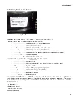
Page 9: ...K30336 The serial number reads as follows 1 engineering level L month of production A Jan B Feb C Mar D April J Dec 21 day of the month 0 last digit of the year repeats every decade K plant it was built in K Tupelo MS 3 assembly line number 0336 sequence number Technical and service information is available to our company authorized service center personnel through our com pany corporate offices r...

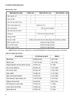
Page 10: ...ditions Drain or preserve fuel Before prolonged storage Fog or lube cylinder Before prolonged storage Rotate engine to TDC Before prolonged storage Fastener Tightening Torques Description U S Measurement Metric Blade Bolt 450 600 in lb 50 70 Nm Wheel nuts 130 170 in lb 12 18 Nm Height adjuster link shoulder screws 45 50 in lb 6 7 Nm Front axle retainers 40 50 in lb 3 5 4 5 Nm Front axle cover 30 4...

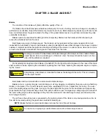
Page 11: ...lete engine or replac ing the mower Bent blades and bent crankshafts are seldom warrantable damage Blades come in a variety of styles side discharge mulching bagging combination there are even de thatching blades on the market The C and D Series mowers come equipped with a 3 in 1 blade from the factory The outer part of the leading edge cuts the grass A wing on the back edge lifts the grass for th...

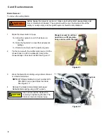
Page 12: ...tool NOTE MTD blade holding tool part number 490 850 0005 can be used block the blade See Figure 2 2 4 Remove the blade bolt and diamond shaped Belleville blade spring using a 5 8 wrench WARNING WARNING Before tipping the mower to work on it make sure it will not start unexpectedly spill fuel or create a burn hazard The engine should be cool the fuel tank should be empty or nearly empty and the ig...

Page 13: ...es drive features on the blade adaptor The blade bolt should not be damaged and the bellville spring that fits between the bolt head and the blade should still have tension 9 Install the blade with the blade adapter and Belleville spring washer properly positioned See Figure 2 4 The part number and the word BOTTOM should face the ground when the mower is in its normal operating position The wings ...

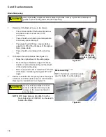
Page 14: ...riginal cutting edge Remove equal amounts of metal from both ends of the blade maintaining the original 29 to 32 angle 3 Balance the blade after sharpening dress the edge of whichever end of the blade is heavier until the blade stays level on the balancer See Figure 2 6 NOTE MTD blade balancer AR SBB 102 or the blade balancing kit AR BSK 1 can be used to balance the blade Use proper safety equipme...

Page 15: ...pping may not perform as intended The belts used on the C D series mowers come from various belt manufacturers but are made to MTD specifications These specifications are tailored to the mower design and seldom work out to standard belt lengths If MTD went to the trouble and expense of designing a belt for the application there is a rea son they did so NOTE If the belt has broken prematurely ident...

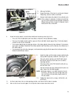
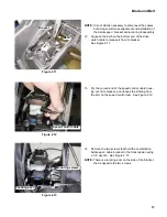
Page 16: ... cover Tilt the back of the cover up and draw the cover back to release the tabs that locate the front edge of the cover 9 Lift the transmission cover off of the mower See Figure 2 9 10 Unhook the loop in the drive clutch cable from the post that the upper belt cover screw goes into 11 Unhook the clutch release spring from the brackets that hold it and remove it from the mower See Figure 2 10 Figu...

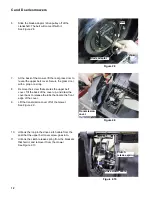
Page 17: ...re 2 11 13 Pry the curved end of the speed control cable hous ing out of its bracket and unhook the Z fitting from the arm on the speed control cam See Figure 2 12 14 Remove the two screws that hold the combination belt keeper cable bracket to the transmission using a 1 4 wrench See Figure 2 13 NOTE There is a locating post on the side of the bracket that is opposite the two screws Figure 2 11 Bra...

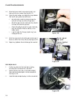
Page 18: ...polished contact surfaces or belt debris dust Look for signs that foreign objects may have damaged the belt 17 Work the speed control cam through its full range of travel to confirm that it move freely See Figure 2 15 18 Repair any problems that will damage the new belt Belt Replacement 1 Put the new belt onto the transmission pulley extending the belt toward the crankshaft 2 Slip the belt into th...

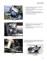
Page 19: ...rews 5 Reinstall the clutch control cable the ground speed control cable and the clutch release spring See Figure 2 18 6 Rock the transmission back or squeeze the clutch lever to tighten the belt 7 Install the lower belt cover being careful to route the belt inside of all four metal belt guide pins that are molded into the cover See Figure 2 19 Figure 2 17 Left leg Locating post Right leg Figure 2...

Page 20: ...tall the transmission cover and test run the mower in a safe area See Figure 2 22 10a Test all operational and safety features before returning the mower to service 10b Adjust the thumb roller on the bottom side of the speed control assembly to set the correct belt tension Rolling the adjuster toward the front of the mower will increase belt tension There is an embossed arrow pointing in this dire...

Page 21: ...ially under 3 200 or at all over 3 200 RPM adjust the engine speed accord ing to the engine manufacturer s instructions 3 Release the safety bail and check the amount of time it takes for the blade to stop rotating NOTE The CSPC Code of Federal Regulations 16 part 1205 dictates that the blade should stop rotating within 3 seconds of releasing the safety bail 4 If the blade does not stop within 3 s...

Page 22: ... the hole and release the pressure See Figure 3 3 4 Unhook the Z fitting from the safety bail NOTE The opposite side of the bail has a 1800 bend in it so that it hooks into the handlebar 5 If the safety bail is to be removed After the z fitting is unhooked pivot the bail upwards to release the hooked end from the right side of the handlebar See Figure 3 4 6 Pry the cable clip off of the handlebar ...

Page 23: ...the mower s safety features before returning it to ser vice Do not return an unsafe mower to service Drive Control Housing Assembly Description The drive control housing on the C and D Series mowers is unique in that it has two drive clutch levers and a 4 position speed control lever The two clutch levers allow operation with either hand See Figure 3 7 The operational description will be broken by...

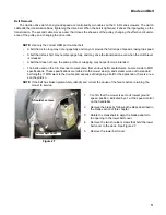
Page 24: ...f travel This change in the path of travel changes the amount of tension on the belt To compensate for variations in belt clutching tension across the range of ground speed selections the bracket that holds the top of the clutch cable moves in coordination with the speed control lever Drive Control Housing Removal and Disassembly 1 Remove the large wing nuts on the carriage bolts that fasten the u...

Page 25: ...er off of the fulcrum post that it shares with the leftt hand side control lever See Figure 3 13 9 Slip the cable end barrel out of the hole in the sec ondary lever NOTE The levers are embossed with indications of their position and order of assembly into the control box The first parts removed would be the last parts installed The ribbed side of the secondary lever is embossed UP3 The next visibl...

Page 26: ...needle nose pliers to compress and remove the detent spring from the speed control actuator See Figure 3 16 NOTE DO NOT over compress the spring Squeeze it only as tight as is necessary to remove it NOTE Some early production 2011 mowers may have a small flat washer tucked between the flat end of the detent spring and the edge of the control housing This is intentional r Figure 3 14 UP 2 Tall post...

Page 27: ...ith the speed control lever fixed in a bench vise Use padding to prevent damage to the lever 16 Lift the speed control actuator out of the drive control housing See Figure 3 19 NOTE The two slots that the lock tabs pass through to fasten the actuator to the lever are different lengths This makes it impossible to attach the actuator to the lever in the wrong direction 17 At this point the clutch ca...

Page 28: ...control assembly to set the correct belt tension Rolling the adjuster toward the front of the mower will increase belt tension There is an embossed arrow pointing in this direction adja cent to the roller Rolling the adjuster toward the rear of the mower will decrease belt tension Too Tight If the speed control lever jumps from Speed 4 to Speed 3 or from Speed 3 to Speed 2 when the drive clutch le...

Page 29: ...elt keeper bracket above the transmission 6 Lower the grass door 7 Draw the lower end of the clutch control cable out of the opening between the grass door and the rear edge of the deck See Figure 3 24 NOTE The outboard cable is the clutch cable 8 Install the new cable by reversing the steps used to remove the cable 9 Run and test the mower in a safe place before returniong it to service 9a Check ...

Page 30: ... the variable speed pul ley 6 Lower the grass door 7 Draw the lower end of the clutch control cable out of the opening between the grass door and the rear edge of the deck See Figure 3 27 NOTE The inboard cable is the speed control cable 8 Install the new cable by reversing the steps used to remove the cable 9 Set the speed control for position 4 leaving maxi mum slack in the cable 10 Run and test...

Page 31: ...unting posts at each end of the trail shield with the grooves in the trail shield mounting recess on the rear baffle See Figure 4 2 5 Pull down on the trial shield bowing it until the mounting posts can be withdrawn from the mounting recesses in the rear baffle 6 Install the trail shield by reversing the steps used to remove it 7 Test run the mower in a safe area and check all of the safety featur...

Page 32: ...in and torsion spring The bracket pin and spring are available separately but the door will typically be replaced as an assembly 3 Disconnect and ground the spark plug wire to pre vent accidental starting of the engine 4 To remove the side discharge door assembly from the deck remove the single screw that fastens the hinge from beneath the deck using a 3 8 wrench See Figure 4 4 Never operate a mow...

Page 33: ... clearance for removing the hinge pin NOTE There are two extruded bosses on the bottom of the hinge They seat into holes in the mower deck to align the hinge NOTE There is a trough formed near the front leg of the hinge The L shaped tail of the closure spring fits into this trough on assembly See Figure 4 6 6 For assembly Clamp the side discharge door to a workbench top See Figure 4 7 7 Insert the...

Page 34: ... Sereis mowers are available with deck wash fittings These fittings resemble fittings that MTD has used on previous equipment but the mounting is different 2 Removing the quick connect hose coupling reveals the new plastic fitting See Figure 4 9 3 Remove the shoulder screw that holds the fitting to the deck using a 3 8 wrench See Figure 4 10 4 Tilt the fitting away from the screw to remove it from...

Page 35: ...ire to prevent accidental starting of the engine 2 Lift the rear grass door and secure it in the raised position with a block or a cord 3 Grasp the grass door hinge pin with a pair of locking pliers and slide it toward the right side of the mower See Figure 4 11 4 Withdraw the hinge pin inset 5 Lift the grass door off of the mower keeping track of the torsion springs that keep it closed See Figure...

Page 36: ...4 6 Position the rear grass door on the rear sub frame 7 Hook the ends of the left torsion springs over the lip near the front edge of the rear sub frame 8 Press the door down to load the torsion springs 9 Insert the hinge pin from the right hand side See Figure 4 15 It should take roughly 15 lbs 6 kg of force to push the pin If it is significantly looser con sider replacing the complete rear subf...

Page 37: ... be removed are off the ground 3 Remove the wheel nut See Figure 4 17 4 Slide the wheel off of the axle Capture the washers on the front wheels if they are present 5 The front wheels may have special double beveled washers between the wheel and the nut See Figure 4 18 6 Install the wheel by following the previous steps in reverse order NOTE Service wheels may not need the washer Check the fit of t...

Page 38: ...ver See Figure 4 20 9 The wheel cover fastens near the hub Pry out the edge of the wheeel cover to reach the fastening point but removal force should be applied as close as possible to the center of the wheel cover 10 Remove the nut from the axle using a 9 16 wrench 11 Slide the wheel off of the axle See Figure 4 21 NOTE The drive gear is not available as a separate service part though it can be r...

Page 39: ...ar The 10 tooth pinion is taller than the 9 tooth pinion and it will not allow the 11 wheel to seat fully on its axle 13 The dust covers of the 8 wheel and the 11 wheels slip off easily once the wheels are removed See Figure 4 23 14 Assembly notes 15 Reinstall the dust covers and pinion gear if removed NOTE Apply a small amount of a dry lubricant such as graphite or PTFE Tefflon to the axle shaft ...

Page 40: ... series mowers Ser vice procedures are similar 3 The height adjuster link connects to the left side of the axle The wheel bracket on the right side of the axle is a mirror image of the wheel bracket on the left side of the axle including the bolt hole for the height adjuster link 4 A simple lever tool can be made usting some flat stock and a roll pin or bolt 5 Use the tool to relieve any remaining...

Page 41: ...g a 3 8 wrench See Figure 4 26 9 With the retainers off the axle will still be held in place by two spring tabs on each end of the axle See Figure 4 27 10 Press a socket or similar round tool into the gap between each pair of tabs gently spreading them to release the axle See Figure 4 28 Figure 4 26 Front axle Retainer Figure 4 27 Spring tabs Figure 4 28 ...

Page 42: ...o pivot pushing the stub axle toward the ground applying lifting force to the deck See Figure 4 30 13 Push the axle assembly past the plastic spring tabs into the pocket that locates it in the front axle cover 14 When the axle is in position secure it with the axle retainers See Figure 4 31 NOTE The axle retainers are off set When installed correctly the outboard edge of the retainers fits flush a...

Page 43: ... unsafe mower into service Front Axle Cover NOTE The front axle cover is the plastic structure attached to the front of the mower deck The front axle mounts to it 1 Remove the front wheels and axle as described previ ously in this chapter 2 Remove the 5 screws that hold the front axle cover to the mower deck using a 1 2 wrench or a T 40 Torx driver See Figure 4 33 3 Install the replacement front a...

Page 44: ...ntrol cables at the bottom end than at the top Disconnect the speed control and clutch cables as described in Chapter 3 of this manual See Figure 4 35 4 Disconnect the engine control cable as described in Chapter 3 5 Remove both of the wing screws that hold the lower handlebar to the rear baffle See Figure 4 36 6 Withdraw the handlebar from the baffle and put it aside 7 After the handlebar is remo...

Page 45: ...ificant drag and without causing the input shaft or the other output shaft to move If an output shaft will not turn in one direction rotate it slightly in the opposite direction or turn the input shaft counter clockwise to discngage the drive pawl This is normal operation Rotating the input shaft counter clockwise should be possible without significant drag and without caus ing either of the outpu...

Page 46: ...t spring that acts on the front axle will keep tension on the height control link To disconnect the height control link from the wheel bracket on the rear axle iso late the spring tension This will take shear load off of the shoulder bolt that connects the height control link to the rear wheel bracket 5 Block the height adjuster link at the front axle See Figure 4 40 A linkage block tool can be ma...

Page 47: ...Chapter 3 9 Remove the drive belt from the transmission input pulley as described in Chapter 2 See Figure 4 42 10 Position the mower for easy access to the screws that hold the lower axle bracket to the rear baffle See Figure 4 43 11 Remove the 5 screws that hold the lower transmis sion bracket to the rear baffle using a 3 8 wrench NOTE The two screws at each end of the lower axle bracket secure s...

Page 48: ...wheel brackets With both bearings slid toward the transmission housing there will be enough range of move ment to slide the transmission housing toward the right wheel bracket the one without the height adjuster lever When the short drive shaft is clear of the left side wheel bracket angle the transmission out of the bracket and withdraw the long drive shaft from the right side wheel bracket See F...

Page 49: ...or PTFE Tef flon can be used Tighten the screws that hold the lower axle bracket to the rear baffle to 30 40 in lbs 3 5 4 5 Nm Tighten the shoulder screw to a torque of 45 50 in lbs 6 7 Nm 17 Test run the mower in a safe area Check all of the safety features and check the full range of drive speeds before returning it to service Do not put an unsafe mower into service Transmission and variable spe...

Page 50: ...s with less torque but more ground speed than when the sheaves are spread See Figure 4 50 The top sheave is fixed on the input shaft The bottom sheave slides up and down the input shaft in response to the ramp on the white plas tic speed control cam NOTE This procedure can be done without remov ing the transmission from the mower It is illustrated on the bench for the sake of visi bility NOTE Spee...

Page 51: ...eaves are fully closed The hole in the arm of the speed control cam will over lap about half way with they recess in the top of the blue rubber plug when the sheaves are fully closed If there is not enough shimming the mower may not have the full low end of the speed range and the speed control cam may over rotate getting jammed against the back edge of the ramp that raises it If there are too man...

Page 52: ...ug with the cam in the relaxed posi tion sheaves spread See Figure 4 56 11 Clean all of the contact surfaces Insure that the cam moves freely Insure that the lower sheave slides freely on the splines Lubricate very sparingly using a dry graphite or PTFE Teflon based lubricant Do not get lubricant where it is likely to get onto the belt or sheaves Tighten the lock nut to a torque of 100 160 in lbs ...

Page 53: ...o that the lower belt cover can be reached 4 Remove the screws that fasten the lower belt cover to the mower deck using a 3 8 wrench The belt cover can remain in place See Figure 4 57 5 Remove the transmission as described previously in this chapter See Figure 4 58 6 Carefully tip the mower down so that it is resting with the bottom of the deck on the workbench 7 Remove the handlebars as described...

Page 54: ...deck See Figure 4 61 10 On installation confirm that the belt and lower belt cover are properly positioned as the new rear baffle goes in See Figure 4 62 The belt must fit inside of all four guide pins in the lower belt cover Figure 4 60 Rear baffle Rear baffle mounting screws CAUTION CAUTION Wear protective gloves and use cau tion when working near the blade Figure 4 61 Figure 4 62 Guide pins ...

Page 55: ...al processes covered in the section of this chapter that applies to them Install the transmission Install the handlebars and controls Connect the control cables Connect the drive belt Install the wheels 16 Test run the mower in a safe area Check all of the safety features and check the full range of drive speeds before returning it to service Do not put an unsafe mower into service Figure 4 63 Loc...

Page 56: ...s section of the manual they have probably made a mistake 1 The input shaft drives a worm gear within the trans m i s s i o n 2 The worm gear turns a helical gear that drives the axles 3 The helical gear and axles are supported by a pair of axle bearings Blue colored thust washers control axle end play See Figure 4 64 4 The retainer for the bearing that supports the worm gear also has two spring a...

Page 57: ...e the drag plate lags relative to the axle moving the pawl control pin inward engaging drive to the axle When the axle is turning faster than the gear the curved slot forces the pawl control pin out disengaging drive to the axle The drag plate rotates on a shoulder on the axle This non A rotor connects to the short axle 10 Taking the drag plate off reveals the pawl and the rotor See Figure 4 68 Th...

Page 58: ...g retainer When the A side drag plate lags relative to the axle the cam slot pulls the pawl control pin inward engaging drive to the A side rotor and the long axle 13 The A side pawl is held outward by a small magnet that fits in the pinion gear See Figure 4 71 NOTE In this picture the B s are visible on the rotor beacuse we are looking at the outward facing side of the rotor It is correctly posi ...

Reviews: