C and D series mowers
36
Front Axle
To remove and replace the axle:
1.
Remove the wheels by following the procedure
described in the previous section of this chapter.
2.
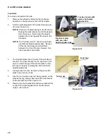
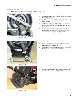
Set the height adjuster to the highest mowing posi-
tion. See Figure 4.24.
NOTE:
There is a lift assist spring on the front axle.
Raising the deck relieves most of the tension
from the spring. It also brings the height
adjuster link to rest against the stop on the
front axle.
NOTE:
The 8” (20cm) and 11” (28cm) rear wheels
use different height adjuster links. Becuse
of this, the front axle geometry differs
between the C and D series mowers. Ser-
vice procedures are similar.
3.
The height adjuster link connects to the left side of
the axle. The wheel bracket on the right side of the
axle is a mirror image of the wheel bracket on the
left side of the axle, including the bolt hole for the
height adjuster link.
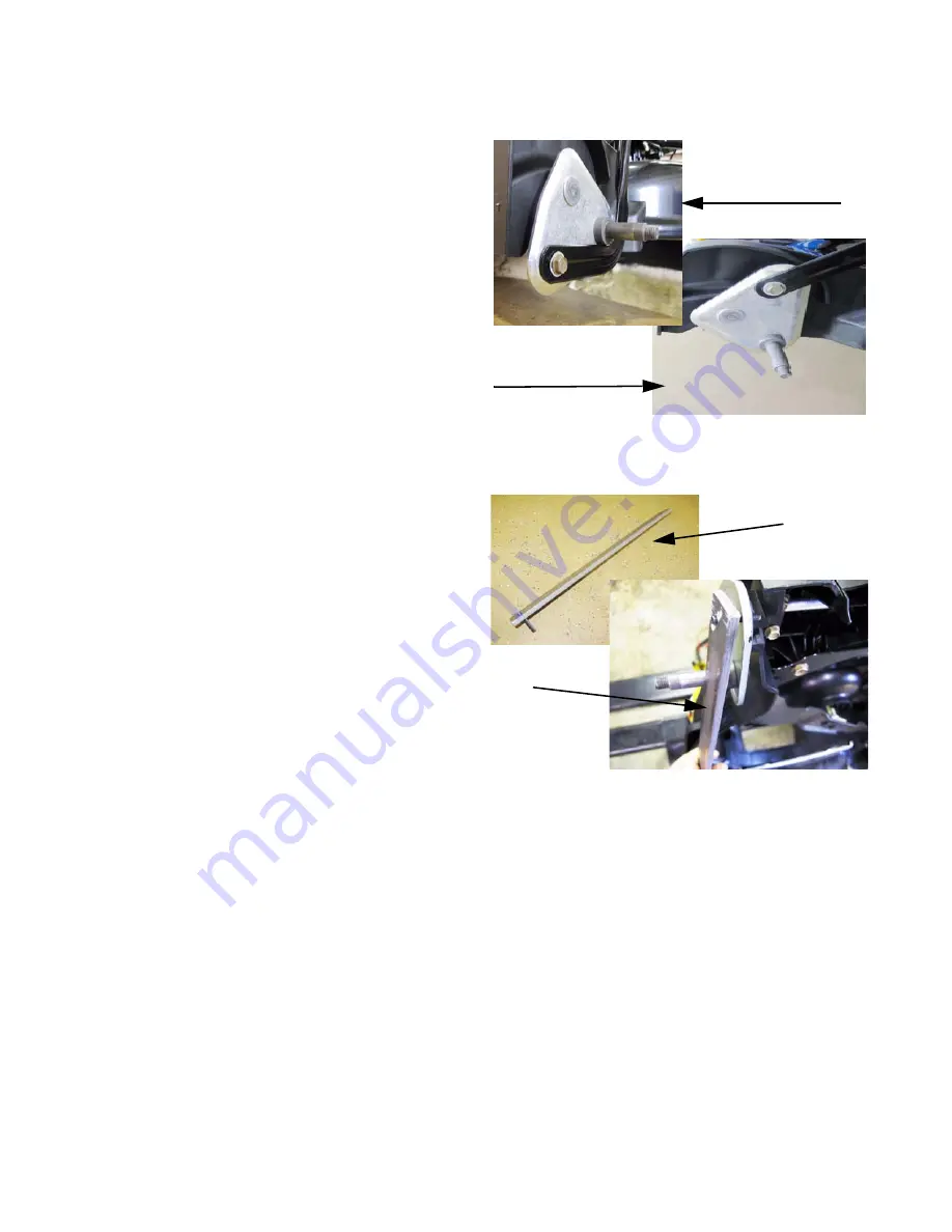
4.
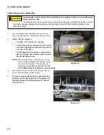
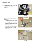
A simple lever tool can be made usting some flat
stock and a roll pin or bolt.
5.
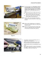
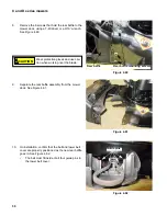
Use the tool to relieve any remaining tension on the
lift assist spring, taking shear load off of the threads
of the shoulder bolt. See Figure 4.25.
6.
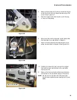
Remove the the shoulder bolt and wave washer that
connect the height adjuster link to the front axle
using a 3/8” wrench.
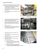
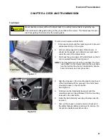
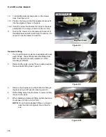
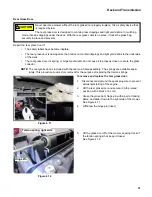
Figure 4.24
C-series mower with
under-shot height
adjuster link.
D-series mower
with over-shot
height adjuster link.
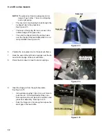
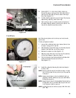
Figure 4.25
Lever tool
Tool in use

