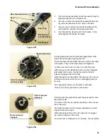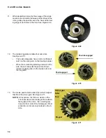
C and D series mowers
46
3.
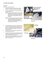
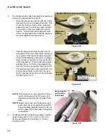
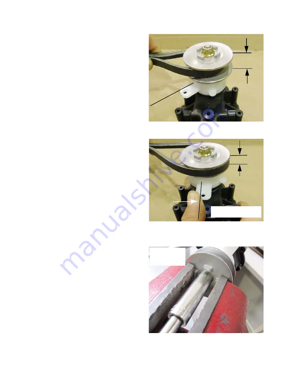
The variable speed pulley opearates by spreading or
closing the gap between the sheaves.
•
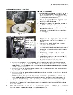
When the gap is wider, the circumference of the
belt contact patch on the pulley is smaller. This
means that each revolution of the crankshaft
pulley will result in a relatively greater number
of revolutions of the input pulley of the trans-
mission. This will drive the wheels with more
torque, but less speed than when the sheaves
are close together. See Figure 4.49.
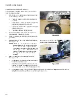
•
Then the sheaves are close together the cir-
cumference of the belt contact patch on the pul-
ley is greater. This means that each revolution
of the crankshaft pulley will result in a relatively
fewer number of revolutions of the input pulley
of the transmission. This will drive the wheels
with less torque, but more ground speed than
when the sheaves are spread. See Figure 4.50.
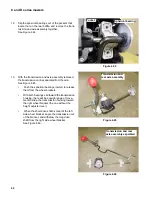
•
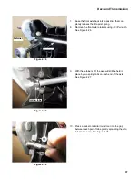
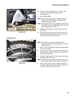
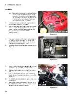
The top sheave is fixed on the input shaft. The
bottom sheave slides up and down the input
shaft in response to the ramp on the white plas-
tic speed control cam.
NOTE:
This procedure can be done without remov-
ing the transmission from the mower. It is
illustrated on the bench for the sake of visi-
bility.
NOTE:
Speed control cam and transmission input
pulley parts are not available through MTD.
The procedures illustrated here may be use-
ful if the assembly is taken apart for cleaning
or lubrication.
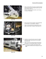
4.
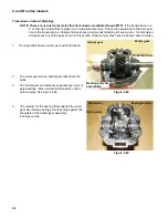
To disassemble the variable speed pulley, hold the
upper sheave with a 1-1/4” wrench, or fix it in a
bench vise. Rotate the nut using a 1/2” wrench.
See Figure 4.51.
Figure 4.49
High speed
position
Sheaves
spread
Smaller effective pulley circumference
Figure 4.50
Low speed
position
Sheaves close
Larger effective pulley
circumference
Figure 4.51
Removing the
nut from the
input shaft

