background image

MSA AUER

MSA 

Use

EVOLUTION 6000 Thermal Imaging Camera

27

US

3.9

EVOLUTION 6000X User Interface and Operation

In addition to the features, functions and options found in the EVOLUTION 6000 and 

EVOLUTION 6000+ models, the EVOLUTION 6000X camera features image and video capture 

capability. 

On-Screen Indicators

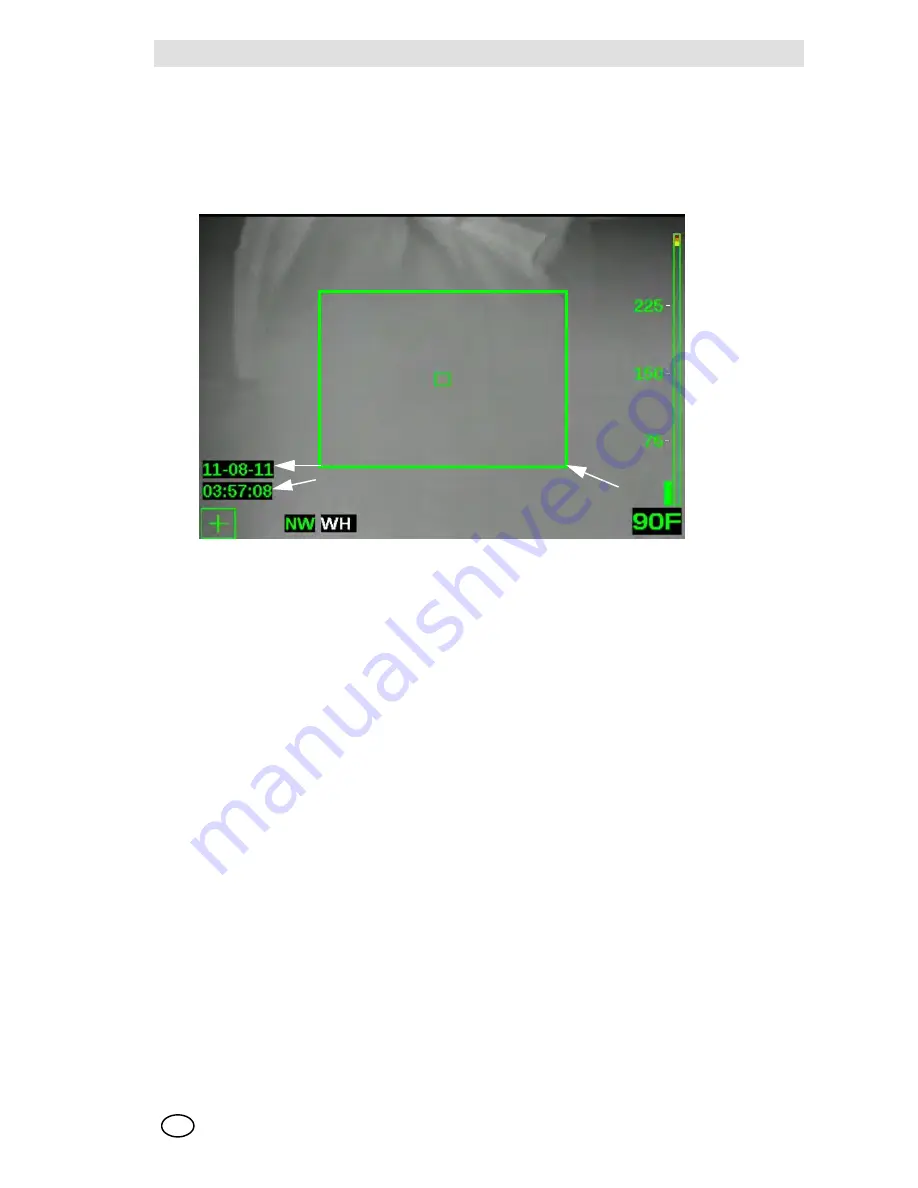
Fig. 10

On-screen indicators

Video Capture

Video capture is available in both the NFPA Basic and NFPA Plus operational modes as it does 

not impact camera operation. When video capture is enabled and turned ON (in camera configu-

ration or via the MSA FireService Utility application), the EVOLUTION 6000X TIC begins record-

ing video in five-minute MPG4 formatted video clips. A time and date stamp on the display 

indicates the start of each new five minute clip. 

NOTE: The time and date stamp does not appear on the display or captured video when the 

EVOLUTION 6000X TIC is in NFPA Basic mode. However, video is still captured if video capture 

is enabled. 

NOTE: The video capture system requires approximately 30 seconds to start up before video is 

captured. Although an image will apear on the screen, no video will be captured during this time. 

In addition, 5-10 seconds of video will not be recorded during the transition from one video clip to 

the next.

Image Capture

NOTE: Image capture is only available in the NFPA Plus operating mode. Activation of image cap-

ture differs, depending on installation of the flashlight/laser pointer option or the range finder option. 

Still images can be captured using the Trigger button and saved to EVOLUTION 6000X TIC mem-

ory for later download to a PC. 

1

Video recording indicator, date and time

2

Image capture

2

1

Summary of Contents for Evolution 6000

Page 1: ...Operating Manual EVOLUTION 6000 Thermal Imaging Camera Order No 10129292 02 ...

Page 2: ...r s instruction Otherwise it could fail to perform as designed and persons who rely on this thermal imaging camera for their safety could sustain serious personal injury or death MINE SAFETY APPLIANCES COMPANY 2013 All Rights Reserved This manual is available on the Internet at www msasafety com Manufactured by MSA NORTH AMERICA 1000 Cranberry Woods Drive Cranberry Township PA 16066 ...

Page 3: ...y Instructions 13 3 2 Switching ON and OFF 13 Switching ON in normal mode function test 13 Switching OFF 13 3 3 Securing the Camera during use 14 NFPA 1801 Basic and Plus Mode Operation 14 3 4 User Interface and Operation All Models 15 On Screen Indicators All Models 15 Battery Status Indicator 18 Battery Charging Indicator 18 Trigger Button 19 3 5 EVOLUTION 6000 TIC User Interface and Operation 2...

Page 4: ...g 31 Truck Mounted Charger 31 Multi Use Charger 32 3 12 Battery Care 33 4 Camera Setup 34 4 1 On Screen Camera Setup EVOLUTION 6000 TIC and 6000X TIC Only 34 4 2 Accessing On screen Configuration Menu 34 4 3 Options 35 Selecting Options 35 Configuring Options 35 4 4 MSA EVOLUTION 6000 Configuration Application 37 Minimum FireService Utility PC requirements 37 Accessing Options and Settings via MSA...

Page 5: ... Determining entry and ventilation points Detection of flashover dangers Search and rescue operations Hazmat situations Overhaul Preplanning Fire code inspections Supporting police work Response vehicle navigation darkness or heavy smoke 1 2 Restrictions The thermal imaging camera is not suitable for the following applications Although the camera is waterproof it is unable to take underwater image...

Page 6: ...Dispose of or recycle in accordance with all ap plicable federal state and local regulations By order of the US Department of Commerce in conjunction with the US Department of State and DOD this Thermal Imaging Camera may not be resold re exported transferred or otherwise dis posed of outside of the country named as the location of foreign end use either in its original form or after being incorpo...

Page 7: ...This thermal imaging camera is not rated as Intrinsically Safe Do not use the system in environments or atmospheres where static or sparks may cause an explosion 6 Before entering a hostile environment test the thermal imaging camera as specified in the instructions to ensure that it is functional After each use inspect the camera to determine if servicing is required 7 Exposure to high temperatur...

Page 8: ...been installed used and main tained in accordance with the instructions and or recommendations contained in the instructions delivered with the equipment MSA shall be released from all obligations under this warranty in the event repairs or modifications are made by persons other than its own or authorized service personnel No agent employee or representative of MSA has any authority to bind MSA t...

Page 9: ...e Remedy It is expressly agreed that the original end user s sole and exclusive remedy for breach of the above warranty for any tortious conduct of MSA or for any other cause of action shall be the re pair and or replacement at MSA s option of any equipment or parts thereof that after examina tion by MSA are proven to be defective Replacement equipment and or parts will be provided at no cost to t...

Page 10: ...e of this manual for assistance Extended warranty requests MUST be exercised within the first 6 months from the date of manufacture The last three characters MYY or month year year of the TIC s serial number located in the battery compartment of the Thermal Imaging Camera dictate this timeframe XX XXXX MYY Extended warranty coverage is available up to 36 months after the standard warranty has ex p...

Page 11: ...320 x 240 uncooled microbolometer heat sensor which provides clear high resolution images equipped with a large screen high definition display equipped with a built in flashlight and laser pointer dustproof and waterproof for short periods submerged under water up to a depth of 3 feet 1 m corresponding to IP 67 able to be configured through a desktop PC through our FireService Utility software ava...

Page 12: ...tely measure distances replaces flashlight and laserpointer if selected offers an optional fully integrated 2 4 GHz or 2 1 GHz depending on local legislation two channel video transmission system Able to be configured on the camera or through a desktop PC using MSA s FireService Utility software Our most advanced camera the EVOLUTION 6000X TIC offers all of the above and also in cludes a fully int...

Page 13: ...utton for approx 1 second Within 5 seconds the TIC carries out a self test of the sensor electronics Status LEDs under display illuminate according to battery status section Battery Sta tus Indicator page 18 The current software version briefly displays An image appears after a few seconds on the display 2 Check camera function Direct the camera toward an object or person until the thermal image s...

Page 14: ...s are compliant with NFPA 1801 Standard on Thermal Imagers for the Fire Service 2013 Edition See approval information on the label located on the underside of the camera housing NFPA 1801 describes a required Basic Mode of operation common among all compliant thermal imaging cameras It also allows for a Plus Mode operation which once accessed provides a number of useful features and options for th...

Page 15: ... features can be custom configured using the MSA Fire Service Utility The EVOLUTION 6000 TIC and EVOLUTION 6000X TIC also include an on screen configura tion feature that allows basic setup modifications to be made without a computer See chapter 4 for details On Screen Indicators All Models Fig 4 On Screen indicators 1 Shutter indicator 5 Digital temperature target 2 Low sensitivity mode indicator...

Page 16: ... necessary to refresh the focal plane array in order to operate properly This occurs via an internal shutter mechanism When the camera shut ters the camera image freezes for approximately one second The shutter indicator is a green square shown at the top left of the display for approx 3 sec before and during the shuttering cycle Pos 1 Fig 4 page 15 Shuttering may occur more frequently with greate...

Page 17: ...d at different temperatures depending on whether the camera is in High or Low Sensitivity mode The Color Reference Bar is only visible for White Hot imagery In High Sensitivity Mode In Low Sensitivity Mode When Temperatures are Objects below 291 F 144 C Are shown as standard gray scale images between 291 F 144 C and 302 F 150 C Turn yellow starting with light shades changing to darker shades betwe...

Page 18: ...icates charging is in progress Green indicates charging is complete NOTE If the indicator is not lit the camera is not in proper contact with the vehicle charger base Ensure that camera is properly installed in the charger and that charger has power Clean the bat tery charging contacts on the front of the camera if necessary WARNING Most electronic devices cease to operate at certain high temperat...

Page 19: ...ent may only be used by properly trained persons Do not aim the laser beam at people If the laser beam falls directly on your eye consciously close your eyes and move your head out of the beam immediately Do not look into the direct or reflected beam Do not aim the laser beam at people Persons under 18 years of age must not use this equipment Safety measures to be applied in areas where the equipm...

Page 20: ...t will not function at the same time NOTE Should the laser beam appear to be weak or distorted ensure that the laser pointer win dow on the front of the camera is free of dirt and water The trigger button also activates the distance meter range finder section Range Finder op tional in the EVOLUTION 6000 and EVOLUTION 6000X Plus Feature page 25 if the camera is so equipped Trigger Button Operation ...

Page 21: ...ng features and functions are common to the EVOLUTION 6000 TIC and EVOLUTION 6000X TIC models Additional User interface and Operating instructions for the EVOLUTION 6000X TIC can be found in chapter 3 9 Fig 7 Additional buttons EVOLUTION 6000 TIC and 6000 X TIC 1 ZOOM button 3 Transmitter indicator LED 2 PALETTE button 3 2 1 ...

Page 22: ...he camera is turned ON push and hold either the ZOOM or the PALETTE button for three seconds until the Plus Mode Indicator appears on the screen Fig 8 All Plus features are now available All applicable indicators appear on screen To return to the Basic mode 1 Briefly push and release the ON OFF button or 2 Turn the camera OFF and back ON again The Plus mode indicator and any applicable feature ind...

Page 23: ...are available 1 Push the PALETTE button to access the available color palettes The Color Palette indicator displays a label for the selected palette Each push of the PALETTE button steps the camera to the next available palette NOTE The color palette loops back to standard white hot after the last available color palette 2 Push and hold the PALETTE button for two seconds to skip immediately back t...

Page 24: ...ompass be calibrated every month or immediately after being subjected to a strong magnetic field Examples of strong magnetic fields include but are not lim ited to power lines transformers strong magnets A compass indicator of CC indicates that compass is out of calibration See section Configuring Options on page 35 for instructions See chapter 4 3 for information on enabling and disabling the com...

Page 25: ...stance is too short WARNING Safety measures which must be observed Observe the appropriate country specific safety measures for users of laser class 3R equipment Laser class 3R laser equipment is potentially hazardous to eyes Use of operating and adjust ment equipment and procedures other than those indicated here can lead to dangerous expo sure to radiation Modification of the laser equipment is ...

Page 26: ...ost a regular annual fee outside the USA The video transmitter indicator is illuminated when the video transmitter is operating Video trans mitter enable and disable as well as channel select are selectable via the on screen setup or the MSA FireService Utility application See section Configuring Options on page 35 for instructions and details regarding the on screen setup options for the video tr...

Page 27: ...s the start of each new five minute clip NOTE The time and date stamp does not appear on the display or captured video when the EVOLUTION 6000X TIC is in NFPA Basic mode However video is still captured if video capture is enabled NOTE The video capture system requires approximately 30 seconds to start up before video is captured Although an image will apear on the screen no video will be captured ...

Page 28: ...5 PM on February 14th 2012 VLC Video Player from VideoLAN free download www videolan org is recommended for open ing and viewing video files Storage Space for Saved Files Videos are saved in a MPEG4 format A minimum of four hours of video can be stored Once the video memory is full new clips overwrite the oldest clips Images are saved in a JPG format A minimum of 1000 images can be stored Once the...

Page 29: ...the camera 4 Locate the USB port labeled A under the battery door and connect the USB cable to this port See Fig 11 The camera appears as an external hard drive on the computer 5 Use the computer to locate the files Video files are stored in the Video folder and the still images are stored in the Pictures folder in the camera 6 Use the computer to move copy and delete files NOTE To prevent overwri...

Page 30: ...ever replace the batteries in a hazardous location or an explosive atmosphere There is a risk of explosion since the batteries can spark when being changed 1 Place the camera on a clean non abrasive surface 2 Open the battery compartment by pulling down on the battery latch and swinging the battery compart ment door forward 3 Place the battery inside the battery compartment with the battery logo a...

Page 31: ... while in the camera To charge the spare battery 1 Insert the battery into the spare battery charging slot 2 Ensure that the charge indicator lights when the battery is inserted A fully depleted battery recharges in the truck mounted charger in approximately 4 hours WARNING Do not charge the batteries in a hazardous location or an explosive atmosphere 1 Place the camera in the truck mounted charge...

Page 32: ...adaptor insert supplied with Multi Use charger is properly in serted in the Multi Use Charger nest Fig 12 2 Ensure that charge indicator light associated with the charging nest being used lights when the battery is inserted Fig 12 Battery insert placement in the Charger nest A fully depleted battery recharges in the Multi Use Charger in approximately 4 hours NOTICE Failure to insert the camera bat...

Page 33: ...ontacts Dirt and debris on the batteries Proper function of the camera charger device and all indicators Cameras and accessories which do not pass this inspection must be removed from service until they have been repaired Batteries which do not pass the test must be replaced NOTE It is recommended to recharge batteries every six months if they have not been in use or if they have not been kept con...

Page 34: ...as a free download from www MSASafety com and with the product CD included with the camera The on screen configuration menu provides a means to change the following Digital temperature target F or C Spotmeter Compass configuration and calibration EVOLUTION 6000 TIC and EVOLUTION 6000X TIC Display brightness Range finder units fee or meters if optional range finder is installed Video Transmitter ON...

Page 35: ...s Compass ON OFF Display Config and Calibra tion if local control was not disabled via MSA FireServ ice Utility package 1 SCROLL to COMPASS ON or COMPASS OFF and SELECT to turn compass ON or OFF 2 SCROLL to SET DISPLAY TYPE TEXT and SELECT to select text icons displayed as N S E W NW etc 3 SCROLL to SET DISPLAY TYPE ICON and SELECT to select a compass icon to indicate direction 4 SCROLL to CALIBRA...

Page 36: ...a returns to the Config main menu Video Xmit Turning optional video trans mitter ON and OFF and se lecting the channel if local control was not disabled via the MSA FireService Utility package 1 To turn video transmitter ON or OFF SCROLL to Set Video Xmit ON or Set Video Xmit OFF Camera front panel video transmit LED illuminates 2 To choose one of the two available video channels SCROLL to Set Cha...

Page 37: ...able disable EVOLUTION 6000 TIC EVOLUTION 6000X TIC Compass directional display options EVOLUTION 6000 TIC EVOLUTION 6000X TIC Video transmitter control including local lockout Video capture control including local lockout EVOLUTION 6000X TIC Set time and Date EVOLUTION 6000X TIC NOTE The available options depend on the EVOLUTION 6000 TIC Minimum FireService Utility PC requirements 1 GHz processor...

Page 38: ...ove the battery 2 Locate the USB port B under the battery door and connect the USB cable Fig 11 page 29 3 Turn ON the EVOLUTION 6000 TIC NOTE The EVOLUTION 6000 TIC must NOT be in the OnScreen Setup mode when using the MSA EVOLUTION 6000 Configuration Application 4 Follow the instructions on the PC Fig 15 TIC Settings ...

Page 39: ...or loose or missing screws O rings or seals Check for cracks and other damage to the display Verify that all device labels are attached 5 2 After Each Use 1 Carefully clean all outside surfaces camera housing including the handles lens display win dow and carrying devices with warm water and a gentle cleaning agent 2 Carefully dry using a soft lint free cloth Avoid scratching the display window 3 ...

Page 40: ...e broken germanium lens and any dirt that may have entered the sealing area 4 Insert the new lens in the retainer and reinstall on the camera 5 Tighten the six screws to 1 6 Nm 14 in lbs of torque WARNING The germanium lens must be replaced immediately after damage is detected Failure to do so may allow water and other contaminants to enter the camera body resulting in a possible loss of camera fu...

Page 41: ...ntative that the product should be returned to MSA 3 Before returning the product decontaminate and clean your Thermal Imaging Camera to re move any hazardous materials that may have settled on the product during use Laws and or shipping regulations prohibit the shipment of hazardous or contaminated ma terials 4 Ship returned products including those under warranty with pre paid transportation cha...

Page 42: ...g time nominal 72 F 22 C EVOLUTION 6000 and EVOLUTION 6000 EVOLUTION 6000X 2 5 to 3 5 hours depending on mode 2 0 to 3 0 hours depending on mode Field of view 48 H 37 V Net equivalent temper ature difference High sensitivity 78 mK 40 mK typical Low sensitivity 234 mK Range Finder Maximum Range 210 ft 70 m Temperature Measurement 10 C 18 F or 10 whichever is greater Image storage Evolution6000X onl...

Page 43: ...er Frequencies and Approvals EN 301 489 Teil 1 3 2000 08 EN 300 440 2V1 1 1 Teil 1 3 2001 09 BAPT 222 ZV 105 106 BAP 122 R1 EMC EN 61000 6 3 and EN 61000 6 2 FCC Part 90 for 2 4 GHz Power at 22 C max 500 mW Transmission Range 1000 m LDS Channel 1 Frequency USA 2474 MHz Channel 2 Frequency USA 2458 MHz ...

Page 44: ...Window Replacement Kit 10145772 USB Configuration video download Cable 10145860 SP Vehicle Mounted Charger Mounting Kit 10040222 Vehicle Mounted Charger Fuses 10145746 SP Wrist Strap 10039516 Shoulder Strap 10039515 Retractable Lanyard 10040226 Carabiner 10040005 Carrying Case 10127441 SP Tripod Mount 10145748 Label Kit Reflective ID 10145749 Fire Station Kit 10145750 Vehicle Kit 10145771 ...

Page 45: ...MSA AUER MSA Ordering Information EVOLUTION 6000 Thermal Imaging Camera 45 US ...

Page 46: ...epublic MSA Safety Czech s r o Dolnojircanska 270 22b 142 00 Praha 4 Kamyk Phone 420 241440 537 Fax 420 241440 537 info cz MSAsafety com Poland MSA Safety Poland Sp z o o Ul Wschodnia 5A 05 090 Raszyn k Warszawy Phone 48 22 711 50 00 Fax 48 22 711 50 19 info pl MSAsafety com Russia MSA Safety Russia Походный проезд д 14 125373 Москва Phone 7 495 921 1370 Fax 7 495 921 1368 info ru MSAsafety com Me...

Reviews: