background image


29 

MCTC manual 

3.10.1


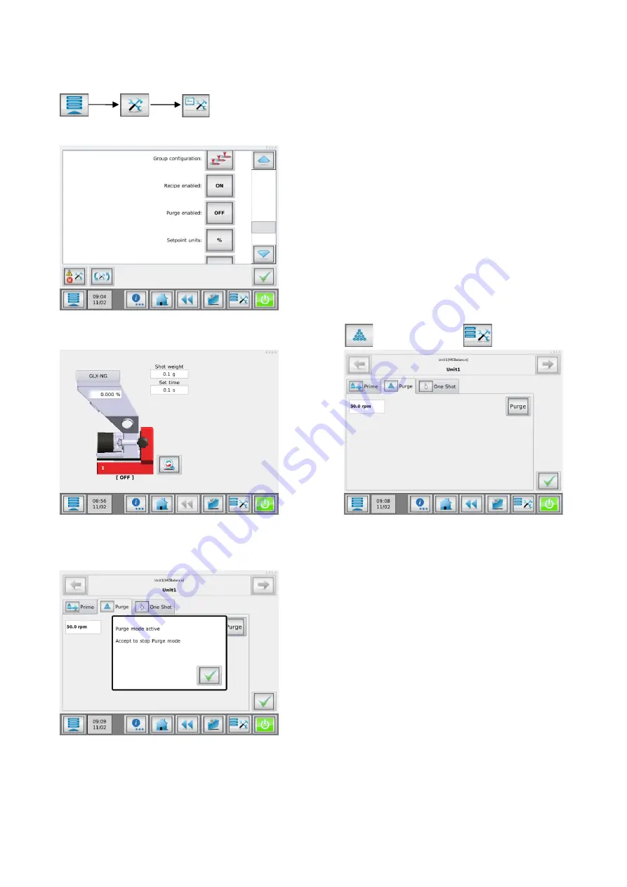
Configure the purge functionality 

By default, the purge function is not available. It needs to be enabled in the system configuration menu (only 
accessible by Supervisor). 


Navigate to the purge enabled, and set 

to “ON”.


Now the purge function can be accessed via the 

Purge

 tab 

 in the Tools menu 


To activate the purge mode

, press the purge button. A “Purge mode active” pop

-up will appear. When the 

“OK” button is pressed, purging is stopped and the display goes back to the

 home screen.  


Summary of Contents for MC-TC

Page 1: ...MCTC manual Software version 2 11 x Manual revision rev 00 Language ENG Date February 2021 ...

Page 2: ...d 20 Quick start configuration after system reset 21 Material files 22 Recipe function 23 3 8 1 Material functions 23 3 8 2 Calculations 23 3 8 3 Calculation examples 24 3 8 4 Recipe editor screen 25 3 8 5 Creating a new recipe 26 3 8 6 Load edit a recipe 26 3 8 7 Deleting a recipe 27 Tools Menu NEW 28 3 9 1 Fill System 28 3 9 2 Prime 28 3 9 3 Purge 28 3 9 4 One Shot 28 Purge function NEW 28 3 10 ...

Page 3: ...TC 44 6 3 3 Example 3 Batch with unloading option activated by pushbutton 45 7 MCTwin 46 Introduction 46 Closed loop 47 7 2 1 Configuration 48 7 2 2 Production 50 Open Loop 52 7 3 1 Production 53 8 Multi component 55 MCTC multi component controller 55 Group structure 56 MCBC blind controller 57 CAN bus connection 58 Alarm warning output 58 Unit controller addressing 59 MCTC remote setup 60 Multi c...

Page 4: ...ge during transport Receipt Check the unit thoroughly upon receipt for damages or missing parts Pass any remarks to the local agent or Movacolor within 8 days upon receipt of goods Disclaimer Movacolor does not warrant that the hardware or software will work properly in all environments and applications and makes no warranty and representation either implied or expressed with respect to the qualit...

Page 5: ...t Always switch off the Movacolor control cabinet and disconnect the mains power plug from electrical power before performing maintenance Dangerous voltages are present inside the control cabinet for up to 2 minutes after it has been switched off Always disconnect the main compressed air connection before performing maintenance Certification The Movacolor dosing unit is designed and produced in co...

Page 6: ...g for start input steady motor running 1 External communication network 2 USB Port 3 Load cell 4 CAN bus cable 5 Start input cable 6 Motor cable 7 Output for Alarm Warning Running 8 Valve output for hopper loader 9 Mains power cable 10 Optional communications 11 Mains power switch 12 Main power indicator 3 2 1 2 3 4 5 6 7 11 9 8 10 1 12 ...

Page 7: ...ows the MC BC in a standard configuration In multicomponent or remote setups refer to chapter Multicomponent 1 Load cell 2 CAN bus cable 3 Motor cable 4 Valve output for hopper loader 5 Mains power cable 6 Mains power switch 7 Mains power indicator 7 6 5 4 3 2 1 ...

Page 8: ...figuration wizard When the machine is powered up for the first time a configuration wizard will pop up In this wizard the date time can be set and a weight tare can be done for each unit For the weight tare it is necessary to have the unit s installed as they will be during production but not yet filled with material Weight tare does not improve the dosing accuracy If the dosing accuracy is a prob...

Page 9: ...table below For some settings the rights can be configured in the Login rights configuration menu For Operator and Tooling level some functionality is limited These limitations can be found in the corresponding chapter User Level Menu access Operator Tooling Supervisor Login Component configuration Active alarms Consumption USB options Advanced settings System configuration Materials Configurable ...

Page 10: ...ho Auto start OFF ON Startup login Operator Tooling Supervisor Login Rights Login rights configuration menu Tooling passw xxxx 1111 Supervisor passw xxxx 2222 IP address 0 0 0 0 For example 192 168 1 100 Netmask 0 0 0 0 For example 255 255 255 0 Gateway 0 0 0 0 For example 192 168 1 1 Nameserver 0 0 0 0 For example 8 8 8 8 MCSmart IP Address 0 0 0 0 For example 192 168 1 10 Screen Time Out OFF ON ...

Page 11: ...r the potential free contact 2 A potential contact 24 Volt DC In case of a powered relay signal wet contact connect the white wire to 24 VDC and the yellow wire to the 0 VDC Note potential contact Guaranteed OFF 0 8VDC Guaranteed ON 18 30VDC 3 A tacho signal up to 30 Volt DC This is used when the dosing system needs to be connected to an extruder that has a tacho generator that produces a voltage ...

Page 12: ... production the motor speed P2 can be changed The new speed is linked to the previous stored voltage and the graph will change accordingly During production the voltage P1 can be adjusted to the current tacho input voltage manually or automatically as shown above The new voltage is linked to the previous stored extruder capacity and the graph will change accordingly The maximum voltage that can be...

Page 13: ...rk environment TCP IP protocol For example 192 168 1 1 When the Movacolor dosing system is part of a network the controller must have a Gateway for accessing the TCP IP network This Gateway address has to correspond with the Gateway address of your computer Ask your network administrator for the correct gateway setting System Configuration Nameserver The nameserver setting sets the IP address of t...

Page 14: ...ration Group Configuration Group selection Displays select the group to be configured Group Configuration Name Group name for example EXTR A max 8 characters Group Configuration Units Set the number of measuring dosing devices within the current group A maximum of 15 components can be configured in total Group Configuration Unit type Unit type selection button by using this button a wizard will st...

Page 15: ...CHigh Output and MCWeight only kg h are displayed when imperial units enabled only parts or lb h can be selected System Configuration Imperial units Imperial units enable disable Set points and actuals displayed in lb h or kg h System Configuration I O module Enable external communication NONE ANALOG PROFIBUS or PROFIBUS requires a special hardware extension board Modbus TCP IP is enabled by defau...

Page 16: ...dosing time only visible in INJ TIMER mode 5 Tools menu In this menu different settings can be made to the system Check the MCTC_Manual_General for more detailed information 6 Start Stop button When the button is colored green the system is OFF safe In red condition the system is ON 7 Toggle button With this button you can toggle between the normal and the detailed view 8 Actual RPM 9 Actual Hoppe...

Page 17: ...EXT RELAY mode 4 Tacho ratio button Here you can link the applied voltage to a extruder capacity only in EXT TACHO mode 5 Tools menu In this menu different settings can be made to the system Check the MCTC_Manual_General for more detailed information 6 Start Stop button When the button is colored green the system is OFF safe In red condition the system is ON 7 Toggle button With this button you ca...

Page 18: ...re detailed information 4 Start Stop button When the button is colored green the system is OFF safe In red condition the system is ON Batch Mode MCNexus 1 Number of pellets to be dosed in one batch 2 Start Stop button When the button is colored green the system is OFF safe In red condition the system is ON 3 Toggle button With this button you can toggle between the normal and the detailed view 4 A...

Page 19: ...ns Over time it can reach an accuracy within 1 of the set point Under normal circumstances the unit will be more accurate than 10 after the first adjustment of the RPM Before the unit makes its first RPM adjustment it might be running already very close to the desired set point because it uses a cylinder and material reference system to determine the first RPM setting This accuracy however cannot ...

Page 20: ...ight As soon the material flow characteristics have been determined 100 of the configured batch weight will be dosed When the dosing accuracy cannot be met a notification will arise mentioning the wrong dosing valve is used or configured Extreme vibrations and shocks influence system performance noticeably Normally the system will be able to compensate for vibrations and shocks Changing set points...

Page 21: ...r of groups 1 15 If installed to one IMM or EXT set to 1 5 Open the group configuration menu 5a Set the number of units for the group 5b Open the component types menu and select the right unit type for each position in the list 6 Confirm all screens 7 Open the device configuration menu 7a Make all required settings consult the appropriate chapter for setting the right settings motor type loader ty...

Page 22: ...t the flow characteristics of the material For optometric systems the file contains information which can be used for consumption counting and dosing quantity For each system new material files can be generated by the user For each dosing system type this material file generation is explained in the dedicated operation chapter of the device The Material files menu can be accessed by pressing the m...

Page 23: ... the amount of Virgin material R Regrind Grinded end product containing the right mix of Virgin and Additives Add Additive Amount additive material related to the Shotweight Batch or total EXT capacity Regrind is defined as Grinded end product containing the right mix ratio of the required materials Other additives will be recalculated depending on the amount of Regrind added to the product mix In...

Page 24: ...r Virgin 250gr 62 5gr 9 4gr 178 1 gr Example 3 Triple MCBalance shotweight 180gr AddV 2 Add 1 Regrind 20 Regrind 180gr 20 36gr Add 180gr 1 1 8gr AddV 180gr 36gr 2 2 9gr Virgin 180gr 36gr 1 8gr 2 9gr 139 3gr Example 4 3 component MCHybrid Batch weight 500gr C1 Vrigin C2 20 Regrind C3 5 AddV 1 MCBalance inline dosing AddV 2 Shotweight 100gr The mix to the injection molding machine will contain Regri...

Page 25: ...earned materials it is recommended to select the Movacolor default material file 6 Material component function how the material should be treated regrind virgin additive 7 Dosing percentage Enter dosing percentage per component To disable a component OFF set the dosing percentage to 0 8 Group selection Select the current group to be edited Only visible when more than one group configured 9 Recipe ...

Page 26: ...to find the recipe It is possible to search in the list of recipes using the search button You can enter part of the recipe name you need to search for Example you need to load the recipe named Recipe RED 1 when you enter RED in the search field all recipes names containing RED will be displayed in the list Confirm the selection with the accept button The next screen will show the settings of the ...

Page 27: ...ipe From the HOME screen press the recipe button from the recipe editor screen choose the list button 1 Select the desired recipe by using the up and down buttons To delete the selected recipe To delete all recipes in the list at once 1 ...

Page 28: ... case of a big barrel size related to the shot weight it is required to purge with already colored material With this purging function the dosing motor of the MCBalance can be started at a pre set speed as long as the purge signal from the Injection Molding Machine is active Be aware of the following remarks Material dosed during purge is not counted by the MCTC consumption counters The purge func...

Page 29: ...iguration menu only accessible by Supervisor Navigate to the purge enabled and set to ON Now the purge function can be accessed via the Purge tab in the Tools menu To activate the purge mode press the purge button A Purge mode active pop up will appear When the OK button is pressed purging is stopped and the display goes back to the home screen ...

Page 30: ...s not as required the speed of the motor during purging can be changed The purge motor speed can be adjusted from the Operator menu In multicomponent setups make sure the right dosing unit is selected prior to entering the prime menu 3 10 4 Purge recipe function It is recommended to use the recipe function the used purge speed can be stored to the recipe For multicomponent systems the purge speed ...

Page 31: ... be changed when purging is activated Purging will be activated for ALL components simultaneously within one group To deactivate a component in a multi component group set the purge speed of the component to 0 RPM Purge function type 2 Purge function type 1 is also available when using purge function type 2 This functionality requires service settings to be changed Contact your distributor or Mova...

Page 32: ... ID will be displayed on this screen A support employee will ask for this ID as it s used to identify the MCTC When pressing the Customer Support button a new window is opened Connect Cancel 1 Connects the MCTC to the remote server Make sure the MCTC meets the usage requirements After pressing the connect button but before the MCTC is connected this button can be used to cancel the active connecti...

Page 33: ...e or disable MCSmart USB logging 4 Remove USB memory stick Safely remove USB memory stick When choosing option 1 import or option 2 export a new screen will be shown with the next options 1 Recipes and Materials Transfer of material and recipe files only 2 Configuration and Settings Transfer of configuration and settings files only 3 Consumption Reports Transfer of consumption reports only export ...

Page 34: ...emoved 3 12 4 Insert USB memory stick When the Remove USB stick option is used but the USB stick is not physically removed from the MCTC it is possible to insert the USB stick again In this way the USB stick does not have to be reinserted to be activated again This might be useful when a MCTC is remotely controlled or when you forgot to copy files The Insert USB stick function can be accessed by n...

Page 35: ...e counted Can be filled in afterwards 2 Group total Total consumption for selected group sum of all components 3 Total Total consumption of the whole machine sum of all groups 4 Group selection Select the current group to be shown Only visible when more than one group configured 5 Component ID The ID and name of the components in the current selected group 6 Material Material name of current loade...

Page 36: ...formation about material usage per group and per component Each time an order number has been changed the consumption counters will be reset At the same time a consumption report will generated and stored to the MCTC internal memory The last 15 generated reports will be stored at the controller See chapter USB menu for the data export function ...

Page 37: ...A soft Alarm is only applicable for a MCHybrid We distinguish 4 different event source levels System events like aux module events production settings errors Group events like main material events Unit events like motor connection failures load cell connection errors CAN bus errors Component events like low hopper event deviation errors Configuration When working with multiple components some conf...

Page 38: ...ton only when logged in as supervisor Tooling login or higher required for recalling this list Events 4 6 1 System events These events apply to the whole system Code Event Description Default 501 AUX module error Cannot connect to AUX module Warning 502 Invalid MCSmart Address Range Wrong IP address for MCSmart server Warning 503 No MCSmart communication Cannot connect to MCSmart server Warning 10...

Page 39: ...w empty level Warning 4002 Low level Hopper level below low level Warning 4003 High high level Hopper level above High High level no RPM regulation Warning 4004 Maximum deviation exceeded Deviation between set and act detected based on a rough weight measurements Warning 4005 Maximum deviation exceeded Deviation between set and act consistently bigger than deviation alarm setting default 25 based ...

Page 40: ... Main Material Sensor is used the alarm event 2001 for this sensor needs to be set Standard the event is configured OFF Refer to chapter Events about how to setup events 5 1 2 Electrical connections The main material sensor has 4 wires brown blue white and black The black wire should not be connected The sensor needs to be connected to input 1 of the MCTC MCTC Terminal Wire color 12 Blue 13 White ...

Page 41: ...e MCTC gives a dosing ready signal Batch mode component configuration Each component in the batch setup can be configured separately When the unloading option is required this should be set in component 1 of the system When the BATCH button of Figure 1 is pressed the screen of Figure 2 appears Figure 1 Component Configuration screen ...

Page 42: ...me before unloading output is activated Example Batch weight 100 g Batch settings as in Figure 2 When the MCTC gets a start input the dosing unit will start dosing at 100RPM when the last 10g Fine Dosing Set is reached the RPMs are changed from 100 to 25 in a time of 2 seconds The dosing unit will continue dosing at 25RPM until the total batch weight of 100 g is reached 6 1 2 Batch unloading In so...

Page 43: ...ight 2 Time unloading output is activated only available when unloading option is enabled 3 Set point unit 1 percentage of the total batch weight 4 Set point unit 2 percentage of the total batch weight 5 Toggle button With this button you can toggle between the normal and the detailed view 1 3 2 4 5 ...

Page 44: ...e Start dosing button is pushed the system starts dosing When dosing is ready a light turns on and unloading can be activated by pushing the unloading button 6 3 2 Example 2 Batch with unloading controlled by MCTC In this example the systems starts dosing when an external start input is given When a batch is ready output 1 will activate input 1 and the batch is unloaded after the loading delay tim...

Page 45: ...m starts dosing when the start button is pressed The start input is controlled by an external relay This relay will interrupt the start input when the unloading valve is activated When unloading is finished the relay will give a new start input to the system for the next batch No external start input is used ...

Page 46: ...nd open loop In closed loop mode the regrind is fed directly from the grinder to the dosing system the dosed amount of colorant is automatically adjusted to the availability of regrind In open loop mode the regrind fed to the dosing system from a big regrind storage tank assuming there is more than enough regrind available Closed loop regrind 4 3 2 1 0 Regrind Color Grinder Neckpiece Virgin Inj Mo...

Page 47: ...e increased automatically The color dosing is lowered according to the amount of regrind dosed to maintain constant coloring When no process disturbance occur the system will continue running in this state If for some reason the amount of regrind fed to the regrind dosing unit increases an operator fills the bin of the grinder manually the regrind unit will increase its dosing In case no regrind i...

Page 48: ... has to be set to Regrind R using the recipe editor From the horizontal menu bar press the recipe button Select material function Regrind 1 and press the save button Next configure the regrind parameters via the Regrind Configuration menu Regrind component configuration Be sure the right component is selected by using the button 1 Max fill level 2 Fill level for Nominal regrind dosing 3 Maximum ti...

Page 49: ...sity 700 gr liter Regrind level 5 x 700 3500gr Method 2 Set Regrind level 500 grams below High level Fill time default 30sec Maximum time the unit tries to load material from the grinder In case a ME or EX loader system is configured this is the maximum time the loader is activated or the knife gate of the support frame is opened In case of a MFD loader this time setting should not be set longer t...

Page 50: ...t 4 Shot weight gr 5 Dosing set time sec Dosing set time only visible in Timer mode otherwise relay time will be displayed 6 Nominal color amount 7 Recalculated color amount reduced by regrind amount 8 Prime Filling the dosing cylinder before start The prime menu appears by pressing Settings speed time can be changed Press confirm to start priming 9 Production Motor On Off Press to start dosing Th...

Page 51: ...culated output kg h gr sec Act Actual additive output kg h gr sec actual additive output is only visible after the first automatic RPM adjustment 2 Speed Actual motor speed RPM 3 Hopper weight Material weight in the hopper 4 Time Set dosing time sec when working TIMER input mode The average dosing time sec when working in RELAY input mode 5 Act Time Count down of the actual dosing time sec 1 1 4 5...

Page 52: ...he regrind unit will not start dosing The color unit will dose it s nominal To start the regrind unit manual activation of the loader system is required The loading system will now Be able to start while the system is switched off When during production no regrind is available the unit will give an alarm As soon as the regrind material hopper is below EMPTY level the regrind unit will stop dosing ...

Page 53: ...t time sec Dosing set time only visible in Timer mode otherwise relay time will be displayed 6 Nominal color amount 7 Recalculated color amount reduced by regrind amount 8 Prime Filling the dosing cylinder before start The prime menu appears by pressing Settings speed time can be changed Press confirm to start priming 9 Production Motor On Off Press to start dosing The motor on off switch will tur...

Page 54: ...lated output kg h gr sec Act Actual additive output gr s or kg h actual additive output is only visible after the first automatic RPM adjustment 2 Speed Actual motor speed RPM 3 Hopper weight Material weight in the hopper 4 Time Set dosing time sec when working TIMER input mode The average dosing time sec when working in RELAY input mode 5 Act Time Count down of the actual dosing time sec 1 1 4 5 ...

Page 55: ...to control and monitor the mixing ratio of these different components from one screen The group functionality enables you control and monitor the feeding of additives in co extrusion co injection setups from one touchscreen Each group with its one start tacho input signal and production parameters Up to 15 groups can be configured easily 4 component system example Component Type Material example 1...

Page 56: ... separately from one touchscreen controller 3 group co extrusion example In this example co extrusion of 3 extruders each with a MCWeight 500 and one MCBalance All controlled from one MCTC This example is used in the next paragraph The units are equipped with MC Blind Controllers 2 MCBC s per extruder 6 in total Software Group navigation Extr A Extr B Extr C ...

Page 57: ...p you need at least one MCTC touchscreen controller and one MCBC blind controller For each additional unit you need an additional blind controller This blind controller is a control box without display and touchscreen and is used to connect to the unit load cell stepper motor valves and sensors The MCTC is used as main controller and uses a CAN bus to communicate to the blind controllers For group...

Page 58: ...hscreen connected to the cable loop Always use Movacolor selected CAN bus cable use of wrong cabling can result in a defective system Alarm warning output In a multicomponent configuration all alarms are centralized to the first unit MCTC UNIT 1 In case of an alarm on a blind controller unit X the alarm output of unit 1 and the alarm output of unit X are activated Number Wire color Function 3 Cabl...

Page 59: ...m with 5 units Unit 1 Unit 2 Unit 3 Unit 4 Unit 5 During operation each blind controller needs to be powered on Even if the unit is not used dosing percentage at 0 The multi component setup needs only one input cable to supply the start and or tacho signal to the system This input cable needs to be connected to Unit 1 In a multi group setup each first unit in a group needs an input cable to supply...

Page 60: ...y This also useful when your machine and touchscreen panel is difficult to reach You can order at Movacolor a special modification kit to convert your MCTC controller into a remote version Ask your Movacolor representative for detailed information MCTC Terminal MCBC Cable connection scheme MCTC TERMINAL MCBC MAINBOARD P Name Color P Name Color 1 Shield Shield 1 GND Black 2 GND Black 2 24VDC Red 3 ...

Page 61: ...u 7 Prime Filling the dosing cylinder before start The prime menu appears by pressing Settings speed time can be changed Press confirm to start priming Each unit must be primed separately select the unit to prime before pressing the prime button 8 Production Motor On Off Press to start dosing The motor on off switch will turn from green to red when dosing is started The start LED blinks when the u...

Page 62: ...ecipe menu 7 Prime Filling the dosing cylinder before start The prime menu appears by pressing Settings speed time can be changed Press confirm to start priming Each unit must be primed separately select the unit to prime before pressing the prime button 8 Production Motor On Off Press to start dosing The motor on off switch will turn from green to red when dosing is started The start LED blinks w...

Page 63: ...r before start The prime menu appears by pressing Settings speed time can be changed Press confirm to start priming Each unit must be primed separately select the unit to prime before pressing the prime button 7 Production Motor On Off Press to start dosing The motor on off switch will turn from green to red when dosing is started The start LED blinks when the units are waiting for an input signal...

Page 64: ... stops running Run Output OUT 2 Normally open contact connection 35 and 36 The RUN signal can be used as a Start Stop condition for the molding machine For example Molding machine can only start in case dosing unit is also started Default the Run output 2 OUT 2 is always on in production mode status Dosing or Standby Production status STANDBY or DOSING output 35 and 36 is CLOSED Production status ...

Page 65: ...rogrammable events can be programmed to an Alarm SoftAlarm or Warning See chapter Events Configuration for configuring events For alarm light connection in multicomponent systems see chapter Multicomponent Alarm warning output Alarm Output OUT 13 Normally open contact connection 34 and 35 Alarm event this output is activated the systems stops running Run Output OUT 14 Normally open contact connect...

Page 66: ...he dosing system does come into specification but seems to be slow Possible causes 1 Extreme vibrations and shocks to the system 2 Extreme low Set point See chapter System performance 3 Check in case of use of an automatic hopper loader if the hoses are connected in the right way Problem The input start signal is connected but the unit does not recognize this start signal Possible causes 1 Check i...

Page 67: ...iltering Battery Used for date time Lifetime without mains power approx 5 years Type CR2354 Input signal s Injection molding Start Stop trigger input potential free or 24VDC Extrusion Start Stop trigger input potential free or 24VDC Tacho input 0 30VDC Note potential contact Guaranteed OFF 0 8VDC Guaranteed ON 18 30VDC Output s Stepper motor max output 2A or 4A high torque at 48VDC Solid state 24V...

Page 68: ...68 MCTC manual APPENDIX B MCTC Dimensional drawing ...

Page 69: ...69 MCTC manual APPENDIX C Standard electrical connections ...

Page 70: ...tification From serial number 27500 onwards The object of the declaration described above is in conformity with the relevant Union harmonization legislation Machine Directive 2006 42 EC EMC Directive 2014 30 EU RoHS 2011 65 EU The following harmonized standards and technical specifications have been applied EN 60204 1 Safety of machinery Electrical equipment of machines Part 1 General requirements...

Page 71: ...71 MCTC manual ...

Reviews: