


IX34208a_e.doc / Aug-09
Page 6 / 40
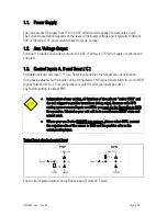
1.4. Relay Outputs
The unit provides two presets with relay outputs (dry change-over), each with a switching
capability of 250 VAC / 1A / 250 VA or 100 VDC / 1A / 100 W respectively.
The response time of the relays is approx. 10 msec.
In case of switching inductive loads it is advisable to use external filtering of the coils.
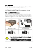
1.5. Serial RS232 / RS485 interface
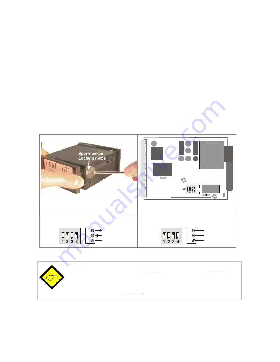
Ex factory the unit is set to RS232 communication. This setting can be changed to RS485
(2-wire) by means of an internal DIL switch. To access the DIL switch, you must remove the
screw terminal connectors and the backplane. Then pull the board to the rear to remove the
PCB from the housing.
ON DIP
DIL-Switch
Removal of the back plane
Location of the DIL switch
RS232:
ON
8
9
10
RxD
TxD
GND
RS485:
ON
8
9
10
A (+)
B (-)
GND
x
Never set DIL switch positions 1 and 2 or DIL switch positions 3 and 4 to
“ON” at the same time!
x
After setting the switch, shift the print carefully back to the housing and
avoid damage of the front pins for connection to the front keypad plate.