


IX34208a_e.doc / Aug-09
Page 5 / 40
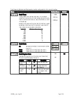
1.1. Power Supply
The unit accepts DC supply from 17 to 30 VDC which must be applied to terminals 1 and 2.
The current consumption depends on the level of the supply voltage and is typically 130mA at
30V or 190mA at 17V, plus currents taken from aux. output).
1.2. Aux. Voltage Output
Terminal 7 provides an auxiliary output of 24 VDC / 120 mA (+/-15%) for supply of sensors and
encoders.
1.3. Control Inputs A, B and Reset ( C )
Standard units use only input “C” as a Reset input and the other inputs are out of function.
In the basic setup menu the inputs can be configured to PNP (signal must switch to +) or to NPN
(signal must switch to -). This configuration is valid for all three inputs at a time.
The factory setting is always PNP.
x
Independent of your setting, all functions of the unit are “active HIGH“ and
the unit triggers to positive transitions (rising edge). Because with NPN
setting open or unused inputs are HIGH, you must tie the Reset line to GND
for operation. Otherwise your unit will be in a continuous RESET state and
cannot work.
x
Where your use 2-wire NAMUR type sensors, please select NPN, connect
the negative wire of the sensor to GND and the positive wire to the
corresponding input.
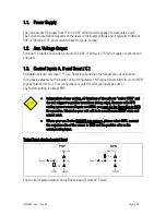
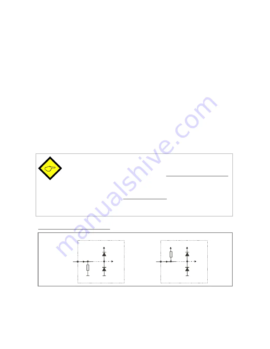
Typical input circuit of control input
PNP
4,7k
GND
GND
+24V int.
Input
4,7k
GND
Input
+24V int.
NPN
The minimum pulse duration on the Reset input (C) must be 5 msec.