General Information
1-2
User’s Manual
1
N
ote
For the MVME197 series, the term Local Bus, as used in
other MVME1xx Single Board Computer series, is referred
to as the Local Peripheral Bus.
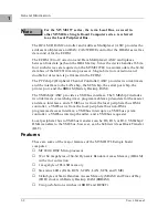
The DCAM (DRAM Controller and Address Multiplexer) ASIC provides the
address multiplexers and RAS/CAS/WRITE control for the DRAM as well as
data control for the ECDM.
The ECDM (Error Correction and Data Multiplexer) ASIC multiplexes
between four data paths on the DRAM array. Since the device handles 16 bits,
four such devices are required on the MVME197LE to accommodate the 64-bit
data bus of the MC88110 microprocessor. Single-bit error correction and
double-bit detection is performed in the ECDM.
The PCCchip2 (Peripheral Channel Controller) ASIC provides two tick timers
and the interface to the LAN chip, the SCSI chip, the serial port chip, the
printer port, and the BBRAM (Battery Backup RAM).
The VMEchip2 ASIC provides a VMEbus interface. The VMEchip2 includes
two tick timers, a watchdog timer, programmable map decoders for the master
and slave interfaces, and a VMEbus to/from the local peripheral bus DMA
controller, a VMEbus to/from the local peripheral bus non-DMA
programmed access interface, a VMEbus interrupter, a VMEbus system
controller, a VMEbus interrupt handler, and a VMEbus requester.
Local peripheral bus to VMEbus transfers can be D8, D16, or D32. VMEchip2
DMA transfers to the VMEbus, however, can be 64 bits wide as Block Transfer
(BLT).
Features
These are some of the major features of the MVME197LE single board
computer:
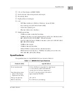
❏
MC88110 RISC Microprocessor
❏
32 or 64 megabytes of 64-bit Dynamic Random Access Memory (DRAM)
with error correction
❏
1 megabyte of FLASH memory
❏
Six status LEDs (FAIL, RUN, SCON, LAN, SCSI, and VME)
❏
8 kilobytes of Static Random Access Memory (SRAM) and Time of Day
(TOD) clock with Battery Backup RAM (BBRAM)
❏
Two push-button switches (ABORT and RESET)
Summary of Contents for MVME197LE
Page 1: ...MVME197LE Single Board Computer User s Manual MVME197LE D2 ...
Page 12: ...xii ...
Page 14: ...xiv ...
Page 22: ...Hardware Preparation and Installation 2 2 User s Manual 2 ...
Page 30: ...Hardware Preparation and Installation 2 10 User s Manual 2 ...
Page 37: ...Memory Maps MVME197LE D2 3 7 3 ...
Page 40: ...Operating Instructions 3 10 User s Manual 3 ...
Page 42: ...Operating Instructions 3 12 User s Manual 3 ...
Page 44: ...Operating Instructions 3 14 User s Manual 3 ...
Page 46: ...Operating Instructions 3 16 User s Manual 3 ...
Page 48: ...Operating Instructions 3 18 User s Manual 3 ...
Page 60: ...Functional Description 4 2 User s Manual 4 ...


