Hard
w
ar
e P
reparatio
n
MV
ME
19
7L
E
/D
2
2-
3
2
MODULE CONNECTOR J1
REMOTE RESET/ABORT/LEDS
CONFIGURATION SWITCH S1
GENERAL PURPOSE/SCON
A32
B32
C32
A32
B32
C32
S2
S3
P1
P2
DS4
DS2
DS1
1A1
VMEbus CONNECTOR P1
FA
IL
LA
N
RUN
A1
B1
C1
A1
B1
C1
DS6
DS5
SC
O
N
DS3
VM
E
SC
S
I
ABORT
SWITCH
S2
RESET
SWITCH
S3
2
1
20
19
1E1
1A17
1E17
1A1
1E1
2A17
2E17
3A1
3E1
3A17
3E17
O
N
1
2
3
4
5
6
7
8
VMEbus CONNECTOR P2
9
O
N
1
2
J1
CONFIGURATION SWITCH S6
SERIAL PORT 4 CLOCK SELECT
S1
S6
MEZZANINE CONNECTOR J2
MVME197LE
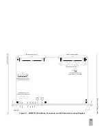
Figure 2-1. MVME197LE Switches, Connectors, and LED Indicators Location Diagram
Summary of Contents for MVME197LE
Page 1: ...MVME197LE Single Board Computer User s Manual MVME197LE D2 ...
Page 12: ...xii ...
Page 14: ...xiv ...
Page 22: ...Hardware Preparation and Installation 2 2 User s Manual 2 ...
Page 30: ...Hardware Preparation and Installation 2 10 User s Manual 2 ...
Page 37: ...Memory Maps MVME197LE D2 3 7 3 ...
Page 40: ...Operating Instructions 3 10 User s Manual 3 ...
Page 42: ...Operating Instructions 3 12 User s Manual 3 ...
Page 44: ...Operating Instructions 3 14 User s Manual 3 ...
Page 46: ...Operating Instructions 3 16 User s Manual 3 ...
Page 48: ...Operating Instructions 3 18 User s Manual 3 ...
Page 60: ...Functional Description 4 2 User s Manual 4 ...


