MVME197LE Functional Description
MVME197LE/D2
4-7
4
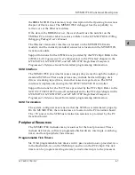
the BBRAM, TOD Clock memory map description in the Operating Instructions
chapter of this manual. The MVME197LE debugger has the capability to
retrieve or set the Ethernet address.
If the data in the BBRAM is lost, the user should use the number on the
VMEbus P2 connector label to restore it. Refer to the MVME197BUG 197Bug
Debugging Package User’s Manual.
The Ethernet transceiver interface is located on the MVME197LE main
module, and the industry standard connector is located on the MVME712X
transition module.
Support functions for the 82596CA are provided by the PCCchip2. Refer to the
82596CA LAN Coprocessor User’s Manual and to the PCCchip2 chapter in the
MVME197LE, MVME197DP, and MVME197SP Single Board Computers
Programmer’s Reference Guide for detailed programming information.
SCSI Interface
The MVME197LE provides for mass storage subsystems through the industry-
standard SCSI bus. These subsystems may include hard and floppy disk
drives, streaming tape drives, and other mass storage devices. The SCSI
interface is implemented using the NCR 53C710 SCSI I/O controller.
Support functions for the 53C710 are provided by the PCCchip2. Refer to the
NCR 53C710 SCSI I/O Processor Data Manual and to the PCCchip2 chapter in the
MVME197LE, MVME197DP, and MVME197SP Single Board Computers
Programmer’s Reference Guide for detailed programming information.
SCSI Termination
The system configurer must ensure that the SCSI bus is terminated properly.
On the MVME197LE, the terminators are located on the P2 transition board.
The +5V power to the SCSI bus termination resistors is provided by the P2
transition board.
Peripheral Resources
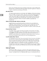
The MVME197LE includes many resources for the local processor. These
include tick timers, software programmable hardware interrupts, watchdog
timer, and local peripheral bus timeout.
Programmable Tick Timers
Six 32-bit programmable tick timers with 1
µ
sec resolution are provided, two
in the BusSwitch, two in the VMEchip2, and two in the PCCchip2. The tick
timers can be programmed to generate periodic interrupts to the processor.
Summary of Contents for MVME197LE
Page 1: ...MVME197LE Single Board Computer User s Manual MVME197LE D2 ...
Page 12: ...xii ...
Page 14: ...xiv ...
Page 22: ...Hardware Preparation and Installation 2 2 User s Manual 2 ...
Page 30: ...Hardware Preparation and Installation 2 10 User s Manual 2 ...
Page 37: ...Memory Maps MVME197LE D2 3 7 3 ...
Page 40: ...Operating Instructions 3 10 User s Manual 3 ...
Page 42: ...Operating Instructions 3 12 User s Manual 3 ...
Page 44: ...Operating Instructions 3 14 User s Manual 3 ...
Page 46: ...Operating Instructions 3 16 User s Manual 3 ...
Page 48: ...Operating Instructions 3 18 User s Manual 3 ...
Page 60: ...Functional Description 4 2 User s Manual 4 ...

