
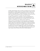


EIA-232-D Interconnections
MVME197LE/D2
A-3
A
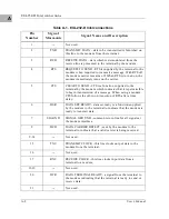
Table A-1. EIA-232-D Interconnections (Continued)
N
otes
1. High level = +3 to +15 volts. Low level = -3 to -15 volts.
2. EIA-232-D is intended to connect a terminal to a modem.
When computers are connected to computers without
modems, one of the computers must be configured as a
modem and the other as a terminal.
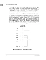
There are several levels of conformance that are appropriate for typical EIA-
232-D interconnections. The bare minimum requirement is the two data lines
and a ground. The full version of EIA-232-D requires 12 lines and
accommodates automatic dialing, automatic answering, and synchronous
transmission. A middle-of-the-road approach is illustrated in Figure A-1.
One set of handshaking signals frequently implemented are RTS and CTS. CTS
is used in many systems to inhibit transmission until the signal is high. In the
modem applications, TRS is turned around and returned as TRS after 150
microseconds. RTS is programmable in some systems to work with the older
type 202 modem (half duplex). CTS is used in some systems to provide flow
control to avoid buffer overflow. This is not possible if modems are used. It is
usually necessary to make CTS high by connecting it to RTS or to some source
of +12 volts such as the resistors shown in Figure A-1. It is also frequently
jumpered to an MC1488 gate which has its inputs grounded (the gate is
provided for this purpose). Another signal used in many systems is DCD. The
original purpose of this signal was to tell the system that the carrier tone from
the distant modem was being received. This signal is frequently used by the
software to display a message like CARRIER NOT PRESENT to help the user
to diagnose failure to communicate. Obviously, if the system is designed
properly to use this signal, and it is not connected to a modem, the signal must
Pin
Number
Signal
Mnemonic
Signal Name and Description
22
RI
RING INDICATOR - RI is sent by the modem to the
terminal. This line indicates to the terminal that an incoming
call is present. The terminal causes the modem to answer the
phone by carrying DTR true while RI is active.
23
---
Not used.
24
TXC
TRANSMIT CLOCK - Same as TXC on pin 15.
25
BSY
BUSY - a positive EIA signal applied to this pin causes the
modem to go off-hook and make the associated phone busy.
Summary of Contents for MVME197LE
Page 1: ...MVME197LE Single Board Computer User s Manual MVME197LE D2 ...
Page 12: ...xii ...
Page 14: ...xiv ...
Page 22: ...Hardware Preparation and Installation 2 2 User s Manual 2 ...
Page 30: ...Hardware Preparation and Installation 2 10 User s Manual 2 ...
Page 37: ...Memory Maps MVME197LE D2 3 7 3 ...
Page 40: ...Operating Instructions 3 10 User s Manual 3 ...
Page 42: ...Operating Instructions 3 12 User s Manual 3 ...
Page 44: ...Operating Instructions 3 14 User s Manual 3 ...
Page 46: ...Operating Instructions 3 16 User s Manual 3 ...
Page 48: ...Operating Instructions 3 18 User s Manual 3 ...
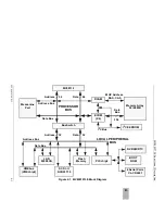
Page 60: ...Functional Description 4 2 User s Manual 4 ...