Performing Installation Tasks
526359-001
MGBI
2-3
Inspecting the Installation Site
Inspect the BSR 2000 installation site to ensure the following:
■
At least 3 in. (7.5 cm) clearance exists on the sides of the BSR 2000 to allow for
adequate airflow for component cooling.
■
At least 3 ft. (1 m) exists at the front and rear panels to connect the Ethernet
cables, upstream and downstream cables, wireless cable, RS-232 Console
Monitor cable, and power cord.
■
The BSR 2000 will be installed within 8 ft. (2.4 m) of an AC power outlet.
■
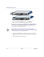
When mounting the BSR 2000 in an equipment rack
, inspect the equipment rack
to determine if it is installed according to the manufacturer’s instructions and is
grounded in accordance with all local, state, and national codes.
■
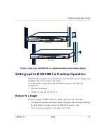
When setting up the BSR 2000 for desktop operation,
confirm that the desktop is
flat, level, and stable and can support 20 lbs. (9 kg). Also confirm that power and
network cables connected to the BSR 2000 will run in areas that will be
undisturbed during operation.
Site Installation Options
The BSR 2000 offers the following site installation options:
■
Mounting in an equipment rack (front mount or mid mount)
■
Desktop installation
Equipment Rack Choices
When you choose to mount the BSR 2000 in an equipment rack, Motorola
recommends using one of the following equipment racks:
■
Standard 7 ft. high, 19-inch equipment racks NEBS or 2200mm ETS1 wide racks
■
Standard 4-post Telco equipment rack.
Note:
You can also place the BSR 2000 on a shelf in an equipment rack. If
you do so, you must attach the rubber feet (found in the BSR 2000 accessory
bag) to the BSR 2000. Refer to the section,
, later in this document.

