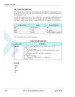


Hardware Information
3-148
G24-L AT Commands Reference Manual
April 15, 2008
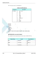
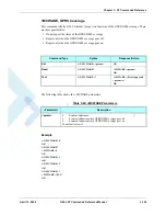
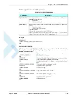
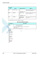
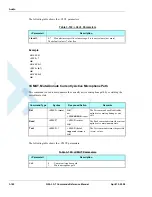
The following table shows the +MIOD parameters.
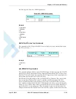
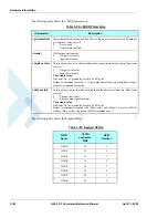
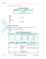
The following table shows the keypad GPIOs.
Table 3-96: +MIOD Parameters
<Parameter>
Description
<pin selection>
Selected pins for the action invoked. This is a binary vector in which each bit points to
pin number. Vector size is 8.
0
Not selected
1
Selected pin (default)
<mode>
GPIO pin operation mode.
0
Output (level only)
1
Input (level mode)
<mode vector>
This is a binary vector in which each bit shows the operation mode of pin. Data vector
size is 8.
0
Output (level only)
1
Input (level mode)
The default value:
On Power Up - as previously saved in FLEX bytes.
Before set command first used - 1. (This means that all lines are configured as Input
before set command first used).
<data vector>
This is a binary vector in which each bit shows the physical value of pin. Data vector
size is 8.
0
Physical low signal.
1
Physical high signal (default).
The default value:
On Power Up - as previously saved in FLEX bytes.
Before set command first used with <Data vector> and <Mode>=0, or after +MIOD
without <Data vector> and MIOD command used - 1.
Table 3-97: Keypad GPIOs
GPIO
Name
70 PIN
connector,
PIN#
GPIO
Number
GPIO1
28
1
GPIO2
30
2
GPIO3
32
3
GPIO4
34
4
GPIO5
36
5
GPIO6
38
6
GPIO7
40
7
GPIO8
42
8
Summary of Contents for AT Commands G24-L
Page 4: ......
Page 20: ...List of Tables xvi G24 L AT Commands Reference Manual April 15 2008 ...
Page 56: ...AT Commands Summary 1 26 G24 L AT Commands Reference Manual April 15 2008 ...
Page 402: ...Tools Overview 5 2 G24 L AT Commands Reference Manual April 15 2008 ...
Page 441: ...W W Index April 15 2008 G24 L AT Commands Reference Manual Index 7 ...
Page 442: ......
Page 443: ......